



Contents: Removal the tapered threaded plug…↓ Removal the valve tappet ↓ Removal the valve ↓ Removal the valve stem seals ↓ Removal valve spring washers ↓ Removal studs ↓ Checking the cylinder head for…↓ Checking the cylinder head for…↓ Checking valve seats ↓ Repair of inlet valve seats ↓ Repair of exhaust valve seats ↓ Checking the axial clearance of the…↓ Checking valve lifters ↓ Checking the oil clearance of the…↓ Checking valve springs ↓ Checking the valves ↓ Nominal overall valve length ↓ Minimum allowable overall valve…↓ Valve stem diameter ↓ Checking the valve stem oil…↓ Nominal oil clearance ↓ Maximum permissible oil clearance ↓ Replacing the valve guide bushing ↓ Nominal oil clearance ↓ Pressing in the guide pin ↓ Installation of fittings ↓ Nominal projection ↓ Installing studs ↓ Tightening torque ↓ Installing valve spring washers ↓ Installing valve stem seals ↓ Installation of valves ↓ Installing valve tappets ↓ Installing Tapered Threaded Plug No.2 ↓ Removal the coolant drain valve…↓ Checking the connecting rod axial…↓ Checking the connecting rod oil…↓ Removal the connecting rods as a…↓ Removal connecting rod bearing shells ↓ Removal piston rings ↓ Removal the piston assembly with the…↓ Removal the crankshaft ↓ Checking the axial clearance of the…↓ Removal the upper thrust half rings…↓ Removal main bearing shells ↓ Removal studs ↓
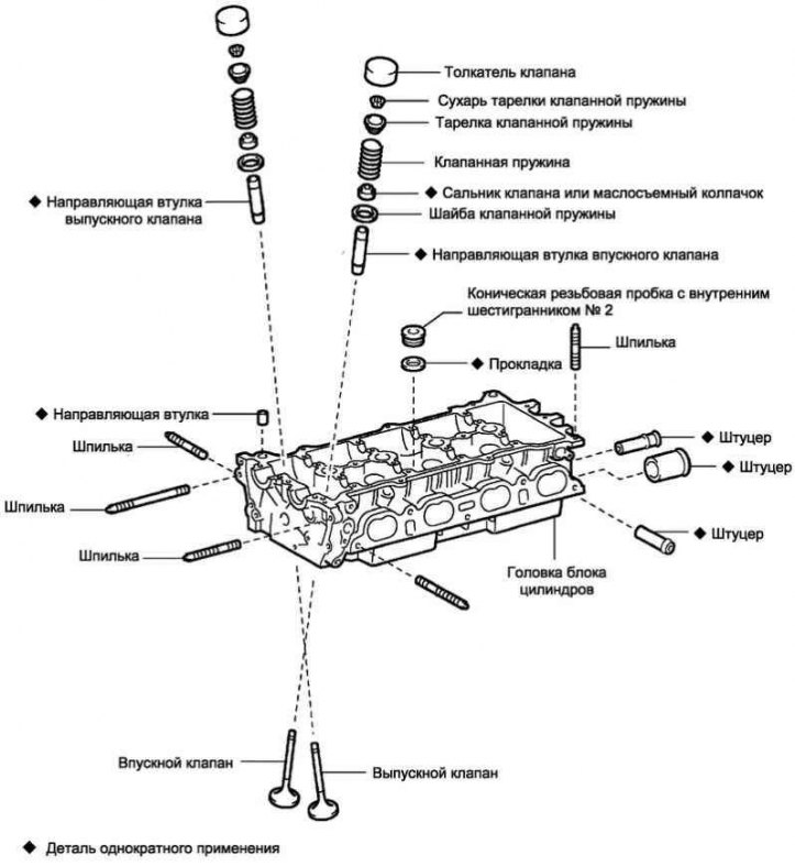
Fig. 2.218. Cylinder head components
Removal the tapered threaded plug No.2
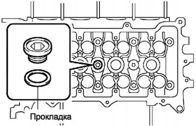
Fig. 2.219. Conical threaded plug
Using a 10 mm Allen key, unscrew the tapered threaded plug and remove the gasket (fig. 2.219).
Removal the valve tappet
Remove 16 valve lifters from the cylinder head.
Removal the valve
Place the cylinder head on wooden blocks.
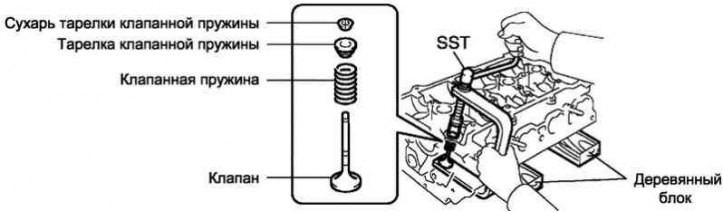
Fig. 2.220. Removing the valve mechanism
Note: Remove all valves from the cylinder head in the following sequence (fig. 2.220).
Using the SST puller, compress the spring and remove the 2 valve spring retainer cotters.
Remove the spring retainers, inner valve springs and valves from the cylinder head.
Removal the valve stem seals
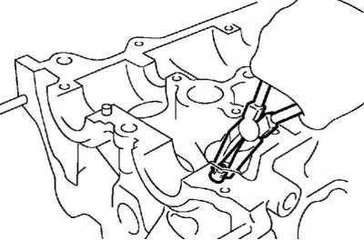
Fig. 2.221. Removing the oil seal
Using fine-nosed pliers, remove 8 oil seals (fig. 2.221).
Removal valve spring washers
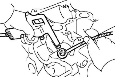
Fig. 2.222. Removing the valve spring washer
Using compressed air and a magnetic rod, remove the 8 valve spring washers (fig. 2.222).
Removal studs
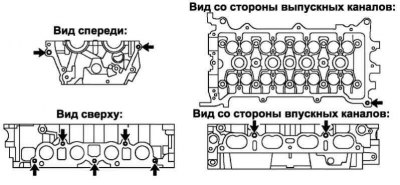
Fig. 2.223. Location of cylinder head studs
Using TORX socket wrenches E5 and E7, remove 10 studs (fig. 2.223).
Checking the cylinder head for deformation
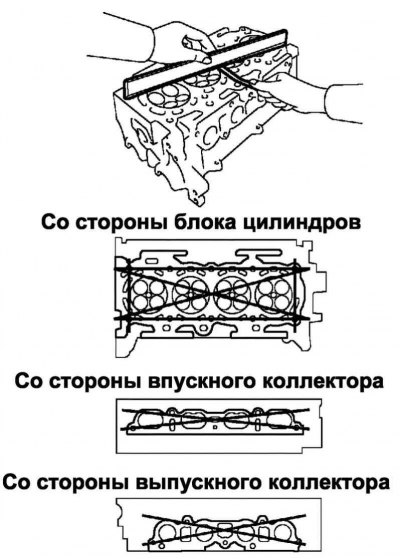
Fig. 2.224. Checking the cylinder head for deformation
Using a precision straightedge and feeler gauge, measure the amount of warpage of the surfaces mating with the cylinder block and manifolds (fig. 2.224).
Maximum allowable warpage value:
- from the cylinder block side - 0.05 mm;
- from the intake manifold side - 0.10 mm;
- from the exhaust manifold side - 0.10 mm.
If warpage exceeds the maximum permissible value, replace the cylinder head.
Checking the cylinder head for cracks and damage
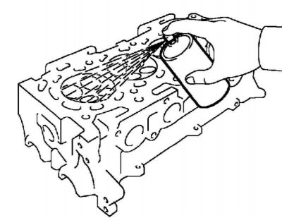
Fig. 2.225. Checking the cylinder head for cracks and damage
Using the developing paint method, check and ensure that there are no cracks in the combustion chamber, intake ports, exhaust ports and on the cylinder block surface (fig. 2.225).
Checking valve seats
Apply a thin layer of Prussian blue or lead white to the valve bevel.
Press the valve lightly against the seat.
Note: Do not rotate the valve.
Check the valve chamfer and valve seat in the order described below.
If a continuous mark is present around the entire circumference of the valve chamfer, the valve disc is not warped. Otherwise, the valve should be replaced.
If a continuous trail of paste is present around the entire circumference of the valve seat, the axes of the guide bushing, valve plate and seat coincide. Otherwise, the valve seat surface should be re-ground.
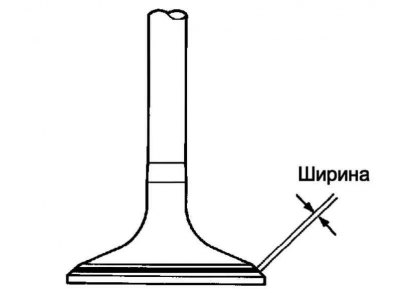
Fig. 2.226. Width of contact zone
Make sure that the valve seat face is in contact with the center of the valve seat surface and that the contact area width is within the nominal value (fig. 2.226).
Repair of inlet valve seats
Using a 45° cutter, ream the valve seat surface in the cylinder head slightly wider than the nominal valve seat contact width (fig. 2.227a).
Note: To achieve a smoother valve seat surface, apply less pressure on the cutter when boring the seats.
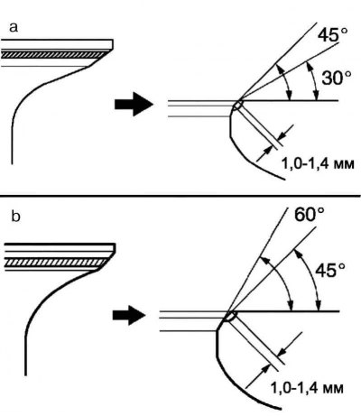
Fig. 2.227. Diagram of the bore of the intake valve seat
Make sure that the valve working chamfer mates with the middle part of the valve seat surface. Otherwise, re-bore the seat surface with a milling cutter with an angle of cutting edges of 45° (fig. 2.227 a).
Machine the valve seat surface with a cutter with a cutting edge angle of 30° or 60° so that the contact area between the seat and the valve chamfer is in the middle of the chamfer.
If the contact area on the valve chamfer is too high, use cutters with cutting edge angles of 30° and 45° to machine the seat (fig. 2.227 b).
If the contact area on the valve chamfer is too low, use 60° and 45° cutters to machine the seat.
Using grinding paste, lap the valve to the valve seat. The work is done manually.
Recheck the valve seat fit.
Repair of exhaust valve seats
Using a 45° cutter, ream the valve seat surface in the cylinder head slightly wider than the nominal valve seat contact width.
Note: To achieve a smoother valve seat surface, gradually reduce the pressure on the cutter when boring the seats.
Make sure that the valve working chamfer mates with the middle part of the valve seat surface. If not, re-bore the seat surface with a milling cutter with a cutting edge angle of 45°.
Machine the valve seat surface with a cutter with a cutting edge angle of 30° or 75° so that the contact area between the valve seat and the valve chamfer is in the middle.
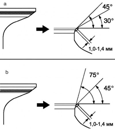
Fig. 2.228. Diagram of the exhaust valve seat boring
If the contact area on the valve chamfer is too high, use cutters with cutting edge angles of 30° and 45° to machine the seat (fig. 2.228 a).
If the contact area on the valve chamfer is too low, use cutters with cutting edge angles of 75° and 45° to machine the seat (fig. 2.228 b).
Using grinding paste, lap the valve to the valve seat. The work is done manually.
Recheck the valve seat fit.
Checking the axial clearance of the camshaft
Install 2 camshafts.
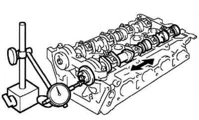
Fig. 2.229. Checking the axial clearance of the camshaft
By moving the camshaft in the axial direction, measure the axial clearance with a dial indicator (fig. 2.229).
- Nominal axial clearance: 0.040–0.095 mm.
- Maximum permissible axial clearance: 0.110 mm.
If the axial clearance exceeds the maximum permissible value, replace the cylinder head. If the camshaft bearing journals are damaged, replace the camshaft.
Measuring the oil clearance of the camshaft journals
Clean 9 bearing caps and camshaft journals.
Install the camshafts into the cylinder head.
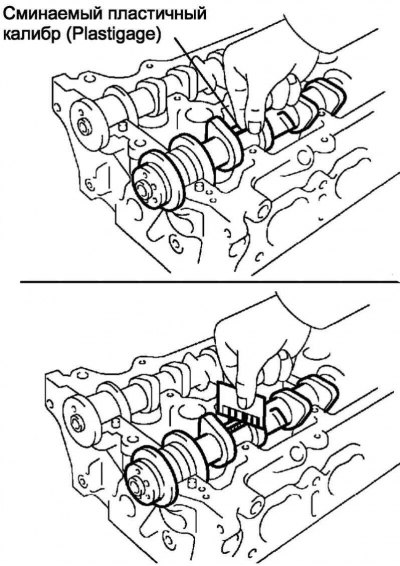
Fig. 2.230. Measuring the oil clearance of the camshaft journals
Place crushable plastic gauges axially on all camshaft journals (fig. 2.230).
Install 9 camshaft bearing caps.
Note: Do not turn the camshafts.
Remove 9 bearing caps.
Measure the crushable plastic gauges at their widest point (fig. 2.230).
- Nominal oil clearance: 0.035–0.072 mm.
- Maximum permissible oil gap: 0.10 mm.
Note: After measuring, completely remove any remaining crumple plastic gauge.
Note: If the oil clearance exceeds the maximum allowable value, replace the cylinder head or camshaft.
Checking valve lifters
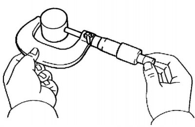
Fig. 2.231. Measuring the valve tappet diameter
Use a micrometer to measure the diameter of the valve tappet (fig. 2.231).
Valve tappet diameter: 30.966–30.976 mm.
If the diameter is not within the nominal value, replace the valve lifter.
Checking the oil clearance of the valve tappets
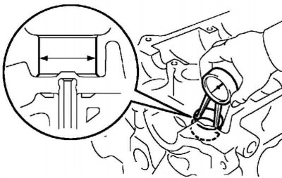
Fig. 2.232. Measuring the valve tappet oil clearance
Use a bore gauge to measure the diameter of the valve tappet seat in the cylinder head (fig. 2.232).
Valve tappet seat diameter: 31.000–31.025 mm.
If the diameter is not within the nominal value, replace the cylinder head.
Subtract the measured valve lifter diameter from the valve lifter seat diameter.
- Nominal oil clearance: 0.024–0.059 mm.
- Maximum allowable oil clearance: 0.079 mm.
If the oil clearance exceeds the maximum permissible value, replace the valve lifter. If necessary, replace the cylinder head.
Checking valve springs
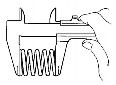
Fig. 2.233. Measuring the length of the valve spring
Use a caliper to measure the overall length of the valve spring in its free state (fig. 2.233).
- Length in free state: 43.40 mm.
If the free length does not correspond to the nominal value, the valve spring should be replaced.
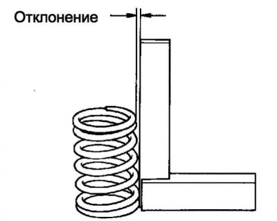
Fig. 2.234. Measuring valve spring perpendicularity
Using a square, measure the perpendicularity of the valve spring (fig. 2.234).
- Maximum permissible deviation: 1.6 mm.
- Maximum allowable angle (for reference): 2°
If the deviation exceeds the maximum permissible value, replace the valve spring.
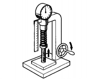
Fig. 2.235. Measuring the compression force of the valve spring
On a special stand, measure the compression force of the valve spring at the nominal length (fig. 2.235).
- Force at nominal length: 158.6–175.4 N at 33.6 mm.
- Maximum working force: 335.3–370.7 N at 24.1 mm.
If the force at the nominal length does not correspond to the specified value, the valve spring must be replaced.
Checking the valves
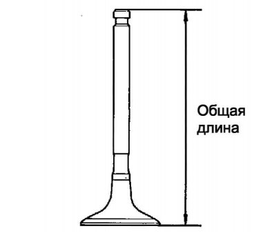
Fig. 2.236. Total length of the valve
Use a caliper to measure the overall length of the valve (fig. 2.236).
Nominal overall valve length
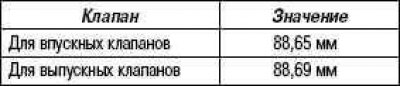
Minimum allowable overall valve length
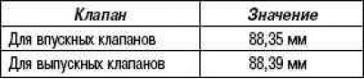
If the overall length of the valve is less than the minimum allowable value, the valve should be replaced.
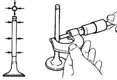
Fig. 2.237. Measuring the valve stem diameter
Use a micrometer to measure the diameter of the valve stem (fig. 2.237).
Valve stem diameter
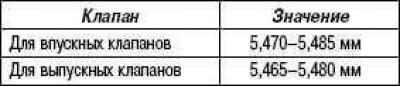
If the diameter does not correspond to the nominal, replace the valve.
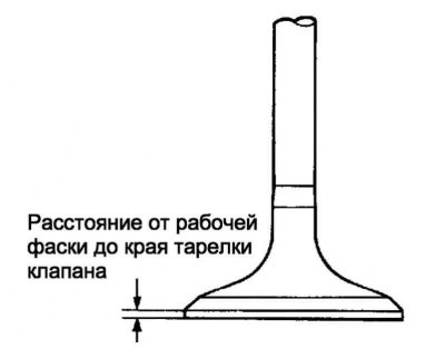
Fig. 2.238. Distance from the working chamfer to the edge of the valve plate
Using a caliper, measure the distance from the working chamfer to the edge of the valve plate (fig. 2.238).
Nominal distance from the working chamfer to the edge of the valve plate: 1.0 mm.
Minimum permissible distance from the working chamfer to the valve plate: 0.7 mm.
If the distance is less than the minimum allowable value, the valve should be replaced.
Checking the valve stem oil clearance in the guide bushing
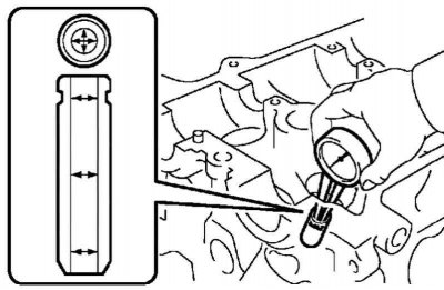
Fig. 2.239. Measuring the internal diameter of the valve guide bushing
Use a bore gauge to measure the inside diameter of the valve guide bushing (fig. 2.239).
Inner diameter of the sleeve: 5.510–5.530 mm.
If the diameter is not within the nominal value, replace the valve guide.
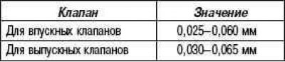
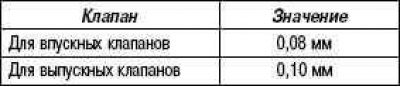
Subtract the measured valve stem diameter from the valve guide inside diameter.
Nominal oil clearance
Maximum permissible oil clearance
If the oil clearance exceeds the maximum allowable value, replace the valve and valve guide.
Replacing the valve guide bushing
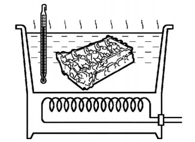
Fig. 2.240. Heating the cylinder head in a special box
Heat the cylinder head to a temperature of 80–100°C (fig. 2.240).
Place the cylinder head on wooden blocks.
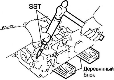
Fig. 2.241. Removing the valve guide bushing
(The information was taken from a web portal Toyotaman.ru)
Using the SST drift, tap out the valve guide bushing (fig. 2.241).
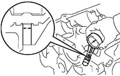
Fig. 2.242. Measuring the diameter of the valve guide bushing seat in the cylinder head
Use a bore gauge to measure the diameter of the valve guide bushing seat in the cylinder head (fig. 2.242).
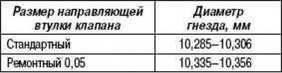
- Diameter: 10.285–10.306 mm.
If the cylinder head bushing bore diameter exceeds 10.306 mm, ream the bore to 10.335–10.356 mm to accommodate an oversize valve guide.
Heat the cylinder head again to 80–100°C.
Place the cylinder head on wooden blocks.
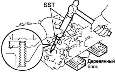
Fig. 2.243. Pressing in a new valve guide bushing
Using the SST tool, press in a new valve guide to the nominal protrusion height (fig. 2.243).
- Protrusion height: 8.7–9.1 mm.
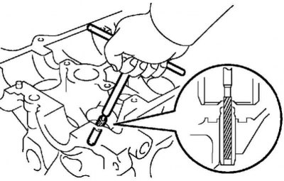
Fig. 2.244. Boring of the valve guide bushing
Using a 5.5mm reamer, ream the valve guide to a size that provides the nominal clearance between the valve guide and the valve stem (fig. 2.244).
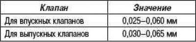
Nominal oil clearance
Pressing in the guide pin
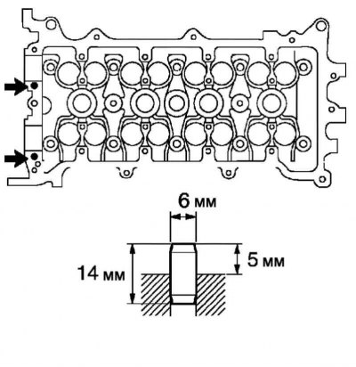
Fig. 2.245. Guide pin pressing diagram
Use a plastic hammer to press in the 2 guide pins (fig. 2.245).
- Nominal protrusion: 5 mm.
Installation of fittings
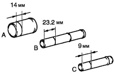
Fig. 2.246. Distance marked with paint
Mark the prescribed position of the fittings with paint (fig. 2.246).
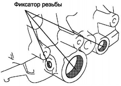
Fig. 2.247. Places of application of fixing grease
Lubricate the holes for the fittings in the cylinder head with locking grease (fig. 2.247).
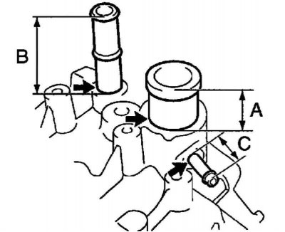
Fig. 2.248. Pressing depth of fittings
Press in the new fittings until the mark is level with the cylinder head surface (fig. 2.248).
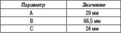
Nominal projection
Note: Press in the fittings within 3 minutes after applying the locking grease.
Add coolant no earlier than one hour after installing the fittings.
Installing studs
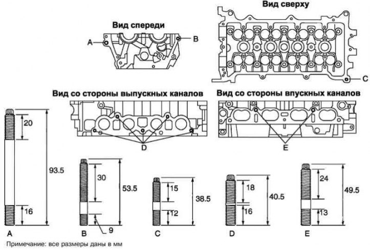
Fig. 2.249. Stud installation diagram
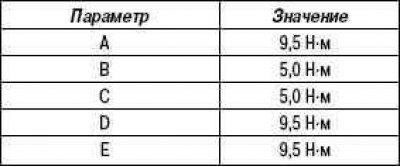
Using TORX socket wrenches E5 and E7, tighten 11 studs (fig. 2.249).
Tightening torque
Installing valve spring washers
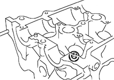
Fig. 2.250. Installing the valve spring washer
Install 8 valve spring washers into the cylinder head cover (fig. 2.250).
Installing valve stem seals
Lubricate the valve stem seals with engine oil.
Note: Be careful not to confuse the valve stem seals for the intake and exhaust valves. Incorrect installation of the valve stem seals may cause malfunction.
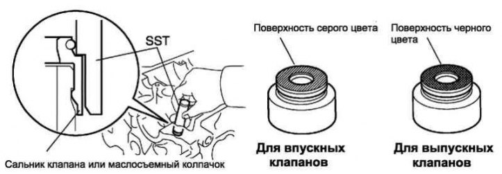
Fig. 2.251. Color marking of oil scraper caps
The intake valve stem seals are painted grey, while the exhaust valve stem seals are painted black (fig. 2.251).
Using SST, install new valve stem seals by hand.
Installation of valves
Install all valves into the cylinder head according to the described procedure.
Place the cylinder head on wooden blocks.
Install the valves, inner valve springs and spring retainers into the cylinder head.
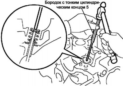
Fig. 2.252. Installing the cracker
Using SST, compress the spring and install 2 valve spring retainer cotters onto the valve stem.
Using punch 5 and a hammer, lightly hit the upper end of the valve stem so that the crackers take the correct position.
Note: Be careful not to damage the end of the valve stem.
Installing valve tappets
Lubricate the 16 valve lifters with engine oil.
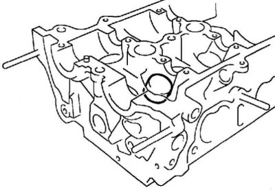
Fig. 2.253. Installing the pusher
Install 16 valve lifters into the cylinder head (fig. 2.253).
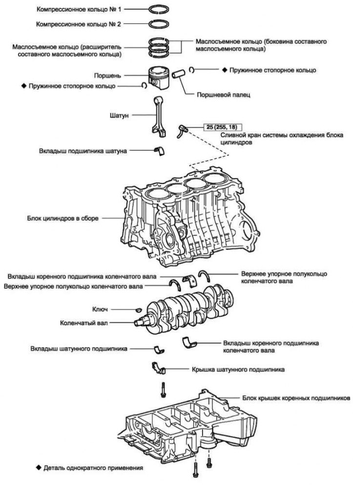
Fig. 2.254. Cylinder block components
Installing Tapered Threaded Plug No.2
Using a 10 mm socket head, tighten the tapered threaded plug with a new gasket.
- Tightening torque: 44 Nm.
Cylinder block overhaul.
Removal the coolant drain valve assembly
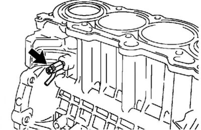
Fig. 2.255. Coolant drain tap
Remove the coolant drain tap assembly from the cylinder block (fig. 2.255).
Checking the connecting rod axial clearance
Turn the crankshaft and set the piston of cylinder No.1 to TDC of the compression stroke.
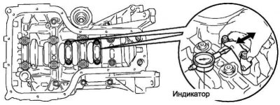
Fig. 2.256. Checking the axial clearance of the connecting rod of cylinders No.2 and No.3
By moving the connecting rod back and forth, use an indicator to measure the axial clearance in the connecting rods of cylinders No.2 and No.3 (fig. 2.256).
- Nominal axial clearance: 0.160–0.342 mm.
- Maximum permissible axial clearance: 0.342 mm.
If the axial clearance exceeds the maximum permissible value, replace the connecting rod.
Replace the crankshaft if necessary.
Turn the crankshaft and set the piston of cylinder No.2 to TDC of the compression stroke.
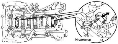
Fig. 2.257. Checking the axial clearance of the connecting rod of cylinders No.1 and No.4
By moving the connecting rod back and forth, use an indicator to measure the axial clearance in the connecting rods of cylinders No.1 and No.4 (fig. 2.257).
- Nominal axial clearance: 0.160–0.342 mm.
- Maximum permissible axial clearance: 0.342 mm.
If the axial clearance exceeds the maximum permissible value, replace the connecting rod.
Replace the crankshaft if necessary.
Checking the connecting rod oil clearance
Turn the crankshaft and set the piston of cylinder No.1 to TDC of the compression stroke.
Measure the oil clearance in the connecting rods of cylinders No.2 and No.3.
Note: Do not rotate the crankshaft during measurement.
Use paint to mark the numbers of the corresponding cylinders on the connecting rods and bearing caps.
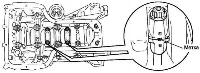
Fig. 2.258. Color marks
Marks on the connecting rods and bearing caps are necessary for correct assembly (fig. 2.258).
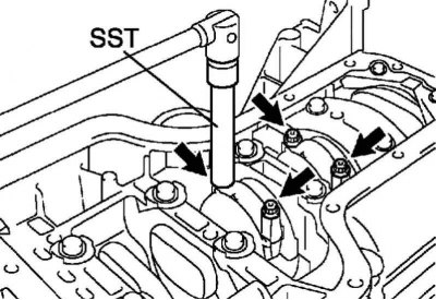
Fig. 2.259. Unscrewing the connecting rod cap mounting bolts
Using SST, remove 4 mounting bolts and 2 connecting rod caps (fig. 2.259).
Clean all connecting rod journals and connecting rod bearing shells.
Check for pits and scratches on the crankpins and bearing shells.
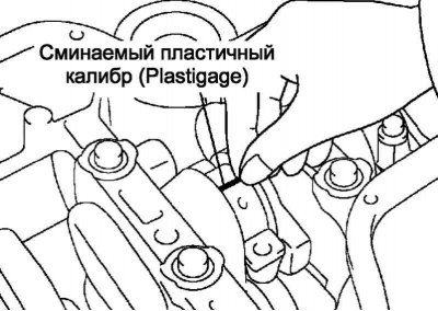
Fig. 2.260. Laying plastic gauge
Place a compressible plastic gauge along the crank pin (fig. 2.260).
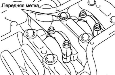
Fig. 2.261. Marks on the connecting rod bearing caps
Make sure the tabs on the connecting rod bearing caps are facing the correct direction (fig. 2.261).
Apply a thin coat of motor oil to the threads and under the heads of the connecting rod cap bolts.
Using SST, tighten the bolts to the specified torque in several steps.
- Tightening torque: 20 Nm.
Mark the front side of each connecting rod cap bolt with paint.
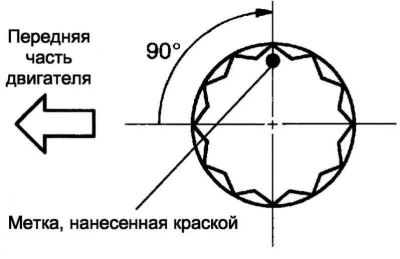
Fig. 2.262. Angle of rotation of the cover mounting bolt
Tighten the cover mounting bolts by 90° as shown in Figure 2.262.
Make sure the crankshaft rotates smoothly.
Using SST, remove 4 bolts and 2 connecting rod caps.
Measure the crushable plastic gauges at their widest point.
- Nominal oil clearance: 0.028–0.060 mm.
- Maximum allowable oil clearance: 0.080 mm.
Note: After measuring, remove the crushable plastic gauges completely.
Note: If the oil clearance exceeds the maximum allowable value, replace the connecting rod bearing shell.
Note: If necessary, grind or replace the crankshaft.
Note: The TAIHO marking is either on the protrusion side or on the opposite side.
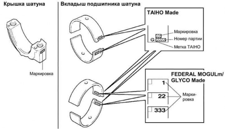
Fig. 2.263. Markings and marks on connecting rod caps and on connecting rod bearing shells
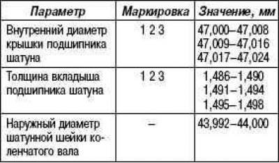
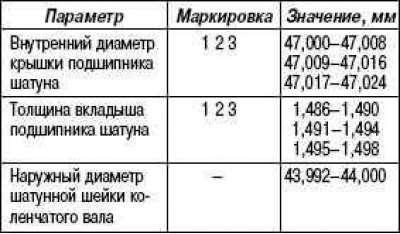
When replacing the bearing shell, select it according to the number stamped on the connecting rod. Bearing shells are supplied in 3 standard size classes, marked with the numbers "1", "2" and "3" respectively (fig. 2.263).
Turn the crankshaft and set the piston of cylinder No.2 to TDC of the compression stroke.
Measure the oil clearance in the connecting rods of cylinders No.1 and No.4 (see fig. 2.258).
Note: Do not rotate the crankshaft during measurement.
Use paint to mark the numbers of the corresponding cylinders on the connecting rods and bearing caps.
Note: Marks on the connecting rods and bearing caps are necessary for correct assembly.
Using SST, remove 4 bolts and 2 connecting rod caps.
Clean all connecting rod journals and connecting rod bearing shells.
Check for pits and scratches on the crankpins and bearing shells.
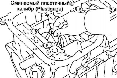
Fig. 2.264. Laying plastic gauge
Place a compressible plastic gauge along the crank pin (fig. 2.264).
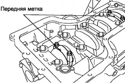
Fig. 2.265. Front marks on the connecting rod bearing caps
Make sure the front marks on the connecting rod bearing caps are positioned correctly (fig. 2.265).
Apply a thin coat of motor oil to the threads and under the heads of the connecting rod cap bolts.
Using SST 09205-16010, tighten the bolts to the specified torque in several steps.
- Tightening torque: 20 Nm.
Mark the front side of each connecting rod cap bolt with paint.
Tighten the cover mounting bolts by 90° as shown in Figure 2.262.
Make sure the crankshaft rotates smoothly.
Using SST, remove 4 bolts and 2 connecting rod caps.
Measure the crushable plastic gauges at their widest point.
- Nominal oil clearance: 0.028–0.060 mm.
- Maximum allowable oil clearance: 0.080 mm.
Note: After measuring, remove the crushable plastic gauges completely.
Note: If the oil clearance exceeds the maximum allowable value, replace the connecting rod bearing shell.
Note: If necessary, grind the journal or replace the crankshaft.
Note: The TAIHO marking is either on the protrusion side or on the opposite side.
Note: When replacing the bearing shell, select it according to the number stamped on the connecting rod. Bearing shells are supplied in 3 standard size classes, marked with the numbers "1", "2" and "3" respectively.
Removal the connecting rods as a whole
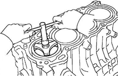
Fig. 2.266. Removing carbon deposits from the upper part of the cylinder
Use a reamer to remove carbon deposits from the top of the cylinder (fig. 2.266).
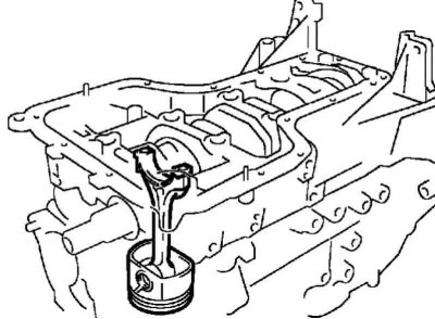
Fig. 2.267. Pushing the piston
Push the piston, complete with connecting rod and upper bearing shell, up and out of the cylinder (fig. 2.267).
Note: The connecting rod bearing shells, connecting rod and connecting rod cap are one set, so they should be placed together.
Note: When disassembling, the pistons and connecting rods should be stacked so that they can be installed in the same places during subsequent assembly.
Removal connecting rod bearing shells
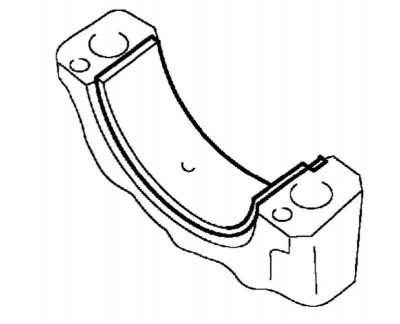
Fig. 2.268. Lower connecting rod bearing shell
Remove the lower connecting rod bearing shell from the cover (fig. 2.268).
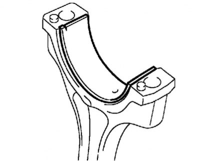
Fig. 2.269. Upper connecting rod bearing shell
Remove the upper connecting rod bearing shell from the connecting rod (fig. 2.269).
Removal piston rings
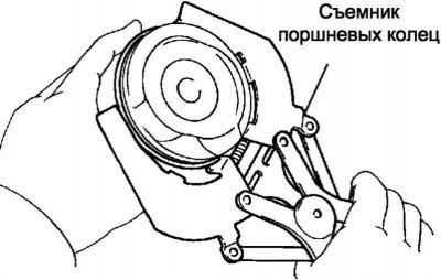
Fig. 2.270. Removing compression rings
Using a piston ring puller, remove the 2 compression rings (fig. 2.270).
Use your hands to remove the 2 sides of the composite oil scraper ring.
Removal the piston assembly with the piston pin
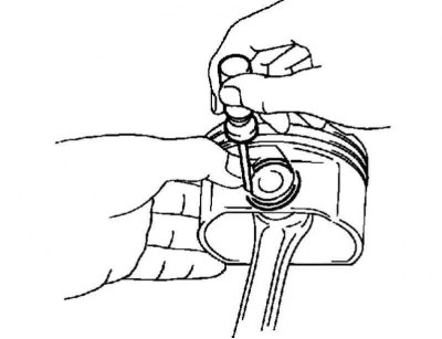
Fig. 2.271. Removing the retaining rings
Using a small screwdriver, remove the 2 snap rings (fig. 2.271).
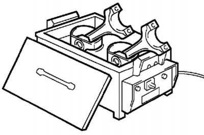
Fig. 2.272. Heating of pistons in a special block
Heat the pistons to 80–90°C (fig. 2.272).
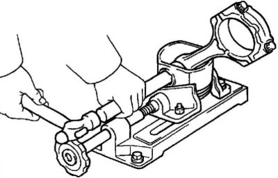
Fig. 2.273. Knocking out the piston pin
Using a plastic hammer and brass rod, carefully tap out the piston pin and remove the connecting rod (fig. 2.273).
Note: Piston pins are selected according to the size of the hole in the piston.
Note: Lay out the pistons, pins, snap rings, connecting rods and connecting rod bearing shells in such a way that they will be installed in their original places during subsequent assembly.
Removal the crankshaft
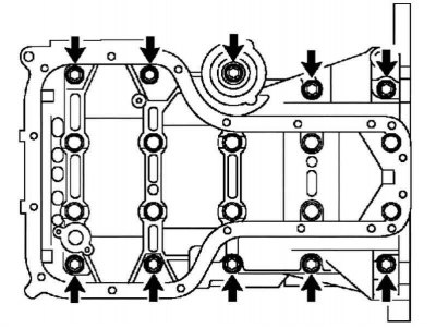
Fig. 2.274. Main bearing cap fastening bolts
Remove 10 mounting bolts from the main bearing cap block (fig. 2.274).
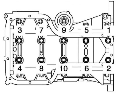
Fig. 2.275. The order of unscrewing the bolts for fastening the main bearing caps
In several steps, evenly loosen and unscrew the 10 bearing cap block mounting bolts in the sequence shown in Figure 2.275.
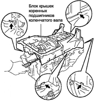
Fig. 2.276. Removing the main bearing cap block
Insert a screwdriver at the indicated points between the cylinder block and the main bearing cap block, and separate the main bearing cap block (fig. 2.276).
Note: Be careful not to damage the mating surfaces of the cylinder block and main bearing cap block.
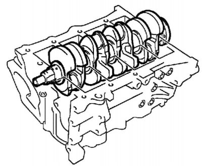
Fig. 2.277. Removing the crankshaft from the cylinder block
Remove the crankshaft from the cylinder block (fig. 2.277).
Checking the axial clearance of the crankshaft
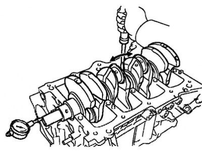
Fig. 2.278. Removing the crankshaft axial clearance
Using a screwdriver, move the crankshaft in the axial direction and measure the axial clearance with a dial indicator (fig. 2.278).
- Nominal axial clearance: 0.04–0.24 mm.
- Maximum permissible axial clearance: 0.30 mm.
If the axial clearance exceeds the maximum permissible value, measure the thickness of the thrust half rings.
If the thickness of the thrust half ring does not correspond to the nominal value, replace the thrust half ring.
Note: Nominal thickness of thrust half ring: 2.430–2.480 mm.
Removal the upper thrust half rings of the crankshaft
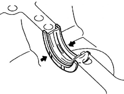
Fig. 2.279. Thrust half rings
Remove 2 thrust half rings from the cylinder block (fig. 2.279).
Removal main bearing shells
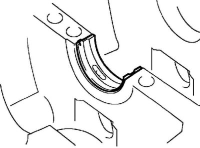
Fig. 2.280. Main bearing shell
Remove 5 main bearing shells from the cylinder block (fig. 2.280).
Note: Lay out the main bearing shells and thrust half rings in the order that allows them to be installed in their original places during assembly.
Removal studs
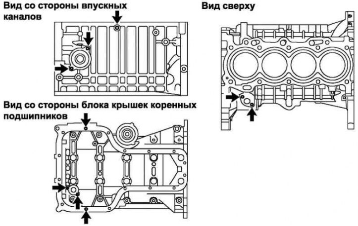
Fig. 2.281. Location of cylinder block studs
Using TORX socket wrenches E5 and E7, remove 9 studs (fig. 2.281).