



Contents: Preparing for disassembly ↓ Disassembly ↓
Preparing for disassembly
1. (Manual transmission) Remove the cover and clutch disc.
2. (Manual transmission) Remove the flywheel.
3. (Automatic transmission) Remove the drive disc.
4. Remove the rear end cover. Remove the two bolts, end cover and dust cover.
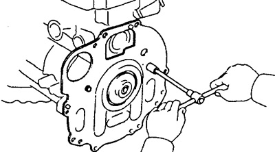
5. Place the engine on the disassembly stand.
6. Remove the generator.
7. Remove the timing belt and pulleys.
8. Remove the cylinder head (see section "Cylinder head").
9. Remove the fuel injection pump (see section "Fuel system").
10. Remove the water pump (see section "Cooling system").
11. Remove the oil pan and oil pump (see section "Lubrication system").
12. Remove the oil cooler (see section "Lubrication system").
Disassembly
1. Remove the four bolts, holder and gasket.
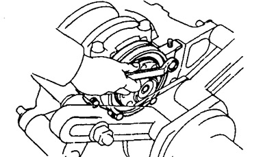
2. Check the connecting rod end play. Using a dial indicator, measure the end play by moving the connecting rod back and forth.
- Nominal axial clearance - 0.08-0.30 mm
- Maximum axial clearance - 0.35 mm
If the axial clearance exceeds the maximum permissible value, replace the connecting rod. If necessary, replace the crankshaft.
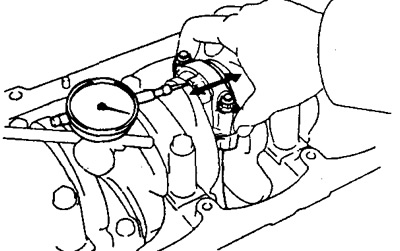
3. Remove the lower connecting rod head caps and check the clearance in the connecting rod journals.
a) Using a center punch or digital stamp, make alignment marks on the connecting rod and cap to ensure proper assembly.
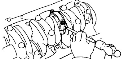
b) Unscrew the nuts securing the connecting rod caps.
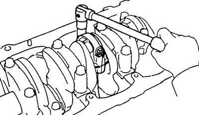
c) Using a plastic-headed hammer, tap the bolts and remove the connecting rod caps.
Publication Reprinted from a web portal: TOYOTAMAN.ru
Note: Leave the connecting rod bearings in place.
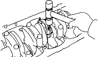
d) Cover the connecting rod bolts with small pieces of hose to protect the crankshaft from damage.
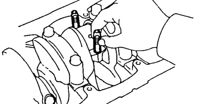
d) Clean the crank journal and bearing.
e) Check the crankpin and bearing for chipping and cracks. If the crankpin or bearing is damaged, replace the bearing shells. If necessary, grind or replace the crankshaft.
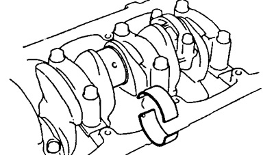
g) Place a piece of plastic gauge along the axis of the crank pin.
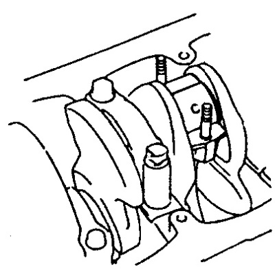
h) Install the connecting rod lower end cap and tighten the nuts. The second pass is a 90° turn.
- Tightening torque - 54 Nm
Note: Do not turn the crankshaft.
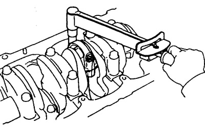
i) Remove the lower connecting rod head cover.
k) Measure the size of the gauge at the point of maximum width, determine the gap.
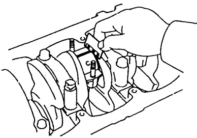
- Nominal neck size: 0.036 - 0.064 mm
Repair #1:
- 2L Engine - 0.023 - 0.073 mm
- 3L Engine - 0.033 - 0.079 mm
Maximum gap: 0.10 mm
If the clearance exceeds the maximum permissible value, grind or replace the crankshaft.
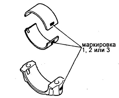
Note: If nominal size bearings are installed, the bearing can be replaced with a bearing of the same number, the marking of which is applied to the lower connecting rod head cover. The standard bearing has one of three sizes, marked "1", "2" and "3" respectively.
Wall thickness at the center point of the bearing shell of nominal size:
- Marking "1" - 1.478 - 1.482 mm
- Marking "2" - 1.482 - 1.486 mm
- Marking "3" - 1.486 - 1.490 mm
l) Completely remove any remaining gauge.
4. Remove the connecting rod and piston group.
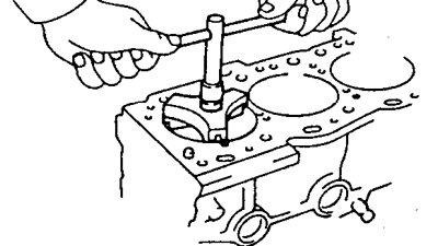
a) Remove carbon deposits from the top of the cylinder.
b) Push the connecting rod-piston group and the upper bearing shell through the top side of the cylinder block.
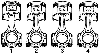
Note: Keep the bearings (liners), connecting rod and cap together. Arrange the piston and connecting rod assemblies in the order of removal.
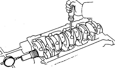
5. Check the crankshaft end play. Using a dial indicator, measure the end play while moving the crankshaft back and forth with a screwdriver acting as a lever.
- Nominal axial clearance: 0.04 - 0.25 mm
- Maximum axial clearance: 0.30 mm
If the axial clearance exceeds the maximum allowable value, replace the thrust bearing.
Thickness of thrust half rings:
- Nominal - 2.430 - 2.480 mm
- Repair No.1 - 2.493 - 2.543 mm
- Repair No.2 - 2.555 - 2.605 mm
6. Remove the main bearing caps and check the main journal-to-bearing clearance.
a) Remove the ten main bearing cap bolts.
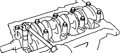
b) Using the removed main bearing cap bolts, move the main bearing cap back and forth, then remove the main bearing caps, lower main bearing shells and lower thrust washers (only in main bearing cap No.3).
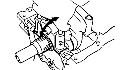
Note: Keep the lower main bearing shell and main bearing cap together.
Arrange the main bearing caps and lower thrust washers in the order of removal.
c) Raise the crankshaft.
Note: Keep the upper main bearing shells and upper thrust washers together with the cylinder block.
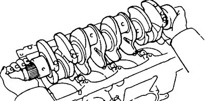
d) Clean the journal and shell of each main bearing.
d) Check the journal and shell of each main bearing for chipping and cracks. If the journal or shell is damaged, replace the bearing shells. If necessary, grind or replace the crankshaft.
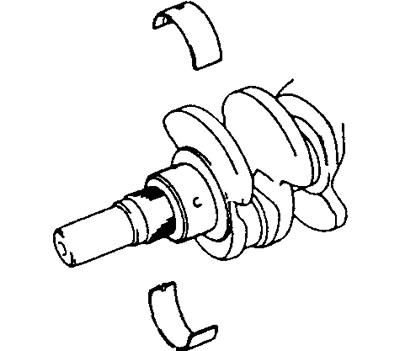
e) Install the crankshaft on the cylinder block.
g) Place a plastic gauge on each neck.
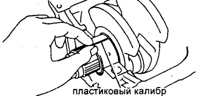
c) Install the main bearing caps (see section "Cylinder block assembly").
- Tightening torque - 103 Nm
Note: Do not turn the crankshaft.
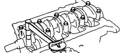
i) Remove the main bearing caps.
k) Measure the size of the gauge at the point of maximum width, determine the gap.
- Nominal size - 0.034 - 0.065 mm
- Repair size No.1 and 2 - 0.033 - 0.079 mm
- Maximum gap - 0.10 mm
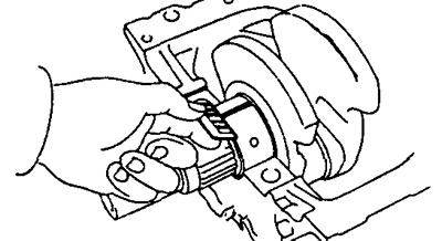
If the clearance exceeds the maximum permissible value, replace the bearing shells. If necessary, grind or replace the crankshaft.
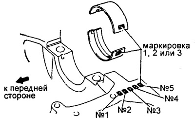
Note: If nominal size bearings are installed, the bearing can be replaced with a bearing of the same number, the marking of which is applied to the rear lower right side of the cylinder block. Standard bearings are divided into three sizes, marked "1", "2" and "3" respectively.
Wall thickness at the center point of a standard size bearing shell:
- Marking "1" - 1.979 - 1.983 mm
- Marking "2" - 1.983 - 1.987 mm
- Marking "3" - 1.987 - 1.991 mm
l) Completely remove any remaining gauge.
7. Remove the crankshaft.
a) Raise the crankshaft.
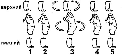
b) Remove the upper main bearing shells and upper thrust half rings from the cylinder block.
Note: Arrange the main bearing caps, bearing shells and thrust washers in the order they were removed.
8. Remove the check valves and oil jets (see section "Lubrication system").