



Note: Thoroughly clean all parts to be assembled.
Before installing parts, apply new engine oil to all sliding and rotating surfaces.
Replace all gaskets, O-rings and oil seals with new parts.
1. Install oil jets and check valves (see section "Lubrication system").
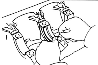
2. Install the main bearing shells.
a) Align the bearing protrusion with the recess in the block and in the main bearing cap.
b) The bearing shell with the hole must be installed in the cylinder block.
3. Install the upper thrust half rings into the recess of the 3rd (L series) or 5th (KZ series) main journal, with the grooves of the half rings facing outward (away from the journal).
4. Install the crankshaft onto the cylinder block.
5. Install the main bearing caps and lower thrust half rings.
a) Install the cover of the 3rd (5th) main bearing with the upper half rings installed in it, the grooves of which should be directed outward (away from the journal).
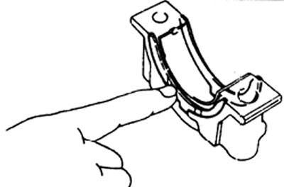
b) Install the remaining covers, taking into account their number and the direction of the arrows, which should be directed towards the nose of the crankshaft.
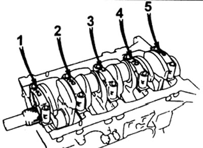
c) Apply a thin coat of engine oil to the threads and under the heads of the main bearing cap bolts.
d) Install and tighten the ten main bearing cap bolts uniformly in several passes in the sequence shown in the figure to a torque of 103 Nm (L series) or in two steps 49 Nm + 90° (KZ series)
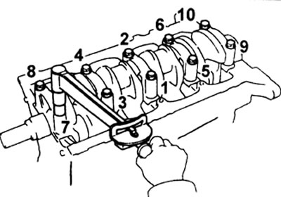
d) Check the smooth rotation of the crankshaft.
e) Check the crankshaft axial clearance (see above).
6. Install the connecting rod and piston group.
a) Cover the connecting rod bolts with short pieces of hose to protect the crankshaft from damage.
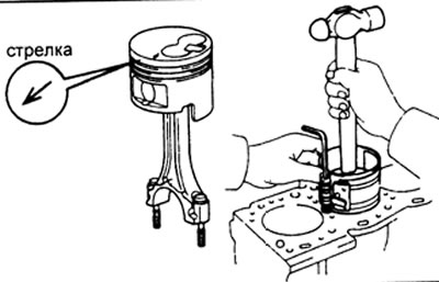
b) Using a piston ring crimper, insert the connecting rod and piston group into each cylinder, observing the numbering.
The arrow on the piston should point towards the front of the engine.
7. Install the connecting rod lower head caps.
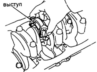
A. Place the cap on the connecting rod.
a) Align the numbered connecting rod cap with the corresponding connecting rod.
b) Install the connecting rod cap in place with the front side marking facing the front of the engine.
B. Install the connecting rod cap nuts. Note: The connecting rod cap nuts are tightened in two successive stages.
If any of the connecting rod bolts are broken or deformed, replace them.
a) Apply a thin coat of engine oil to the threads and under the connecting rod cap nuts.
b) Install and tighten the connecting rod cap nuts one by one, in several passes, to a torque of 54 N·m (L series) or 29 N·m (KZ series).
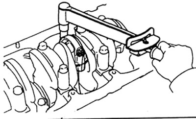
If any of the connecting rod nuts does not meet the tightening torque requirements, replace the nut.
c) Mark the front side of the connecting rod cap nut with paint.
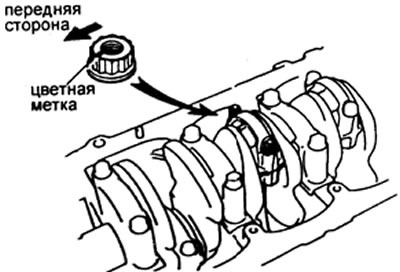
d) tighten the connecting rod cap nuts by 90° as shown in the figure.
Note: (for L series engines only) If new nuts are used, the preliminary tightening torque is 34 Nm, then the nut is turned further by 120°.
d) Check the mark offset by 90° relative to the direction towards the front side.
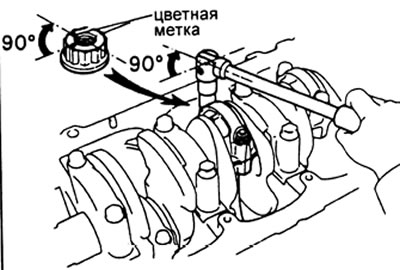
e) Check the smooth rotation of the crankshaft.
See the source on the internet resource toyotaman.ru
g) Check the connecting rod axial clearance.
8. Install the rear oil seal retainer, install a new gasket and retainer with four bolts. Tightening torque 13 Nm.
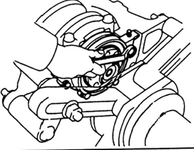
Only for KZ engines
9. Assembling the balance shaft
a) Clamp the shaft in a vice by the counterweight.
b) Install the thrust flange, align the shaft pin with the drive gear hole, put on the gear.
c) Tighten the pinion mounting bolt to 32 Nm.
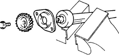
10. Insert both balance shafts into the block, tighten the thrust flange mounting bolts to 8 Nm