
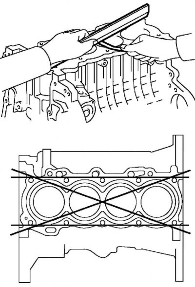
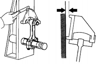
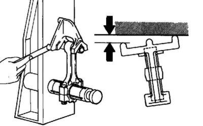
Pic. 2.282. Checking the cylinder block for warpage
Using a precision straight edge and feeler gauge, measure the warping of surfaces mating with the cylinder head gasket (pic. 2.282).
The maximum allowable warp value: 0.05 mm.
If warpage exceeds the maximum allowable value, replace the cylinder block.
Checking cylinder diameters
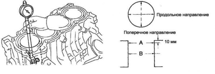
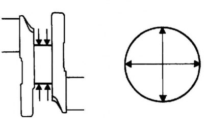
Pic. 2.283. Scheme for measuring cylinder diameter
Using an inside gauge, measure the diameters of the cylinders in planes A and B in the longitudinal and transverse directions (pic. 2.283).
- Nominal diameter: 79.000–79.013 mm.
- Maximum allowable diameter: 79.133 mm.
If the diameter averaged over four dimensions exceeds the maximum allowable value, replace the cylinder block.
Checking the piston assembly with the piston pin
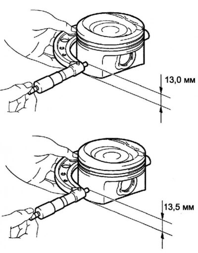
Pic. 2.284. Checking the piston assembly with the piston pin
For 1ZZ-FE engine:
Measure the piston diameter with a micrometer.
Set the micrometer so that it is at a distance of 13.0 mm from the edge of the piston skirt and at a right angle (90°) to the axis of the piston pin holes, as shown in Figure 2.284a.
Piston diameter: 78.955–78.965 mm.
If the diameter is not correct, replace the piston.
For 3ZZ-FE engine:
Measure the piston diameter with a micrometer.
Set the micrometer so that it is at a distance of 13.5 mm from the edge of the piston skirt and at a right angle (90°) to the axis of the piston pin holes, as shown in Figure 2.284b.
Piston diameter: 78.960–78.975 mm.
If the diameter is not correct, replace the piston.
Piston oil clearance check
Subtract the measured piston diameter from the cylinder diameter.
- Nominal oil clearance: 0.073–0.096 mm.
- Maximum allowable oil clearance: 0.10 mm.
If the oil clearance exceeds the maximum allowable value, the piston assembly must be replaced.
If necessary, replace the cylinder block.
Piston pin oil clearance check
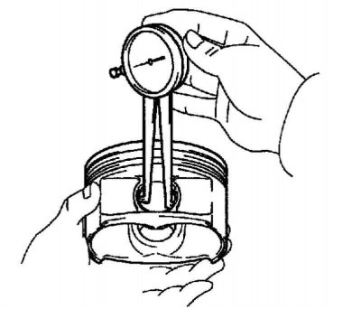
Pic. 2.285. Piston pin bore measurement
Using a dial gauge for bores, measure the diameter of the piston pin bore (pic. 2.285).
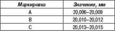
Piston pin hole diameter: 20.006–20.015 mm.
If the diameter is not correct, replace the piston assembly.
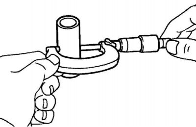
Pic. 2.286. Measuring the outside diameter of the piston pin
Measure the outside diameter of the piston pin with a micrometer (pic. 2.286).
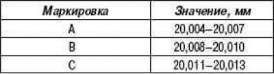
Piston pin outer diameter: 20.004–20.013 mm.
If the diameter is not correct, replace the piston assembly.
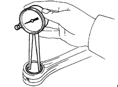
Pic. 2.287. Measuring the bore diameter of the small end of the connecting rod
Using a dial indicator for holes, measure the diameter of the hole in the small end of the connecting rod (pic. 2.287).
Connecting rod small end bore diameter: 20.012 - 20.021 mm.
If the diameter is not correct, replace the connecting rod assembly.
Subtract the measured piston pin outer diameter from the piston pin bore diameter.
- Nominal oil clearance: 0.001 to 0.017 mm.
- Maximum allowable oil clearance: 0.017 mm.
If the oil clearance exceeds the maximum allowable value, replace the connecting rod.
If necessary, replace the piston pin.
Subtract the measured piston pin outer diameter from the piston pin bore diameter.
- Nominal oil clearance: 0.005–0.011 mm.
- Maximum allowable oil clearance: 0.011 mm.
If the oil clearance exceeds the maximum allowable value, replace the connecting rod.
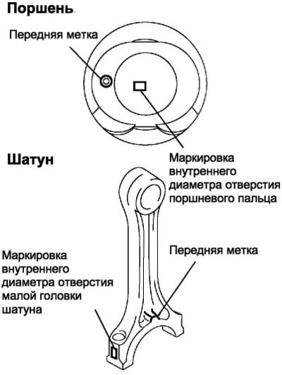
Pic. 2.288. Piston and connecting rod diameter markings
If necessary, replace the connecting rod and piston pin (pic. 2.288).
Checking the clearance between the end face of the piston ring and the piston groove
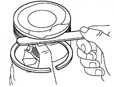
Pic. 2.289. Measuring the gap between the end face of a new piston ring and the wall of the piston groove
Use a feeler gauge to measure the gap between the end face of the new piston ring and the wall of the piston groove (pic. 2.289).
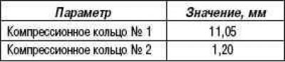
Gap between piston ring face and piston groove
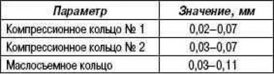
If the clearance is not within specification, replace the piston assembly.
Checking the clearance in the piston ring lock
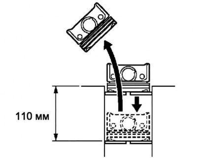
Pic. 2.290. Pushing the piston ring into the cylinder
Using a piston, push the piston ring into the cylinder, slightly short of the bottom of the ring stroke, at a distance of 110 mm from the top plane of the cylinder block (pic. 2.290).
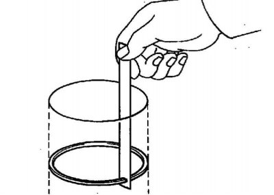
Pic. 2.291. Measuring the gap in the lock of the ring
Measure the ring gap with a feeler gauge (pic. 2.291).
If the clearance in the piston ring lock exceeds the maximum allowable value, replace the piston ring.
Nominal clearance in the piston ring lock
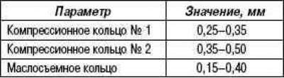
The maximum allowable gap in the lock
If the clearance in the piston ring lock exceeds the maximum allowable value, even with a new piston ring, replace the cylinder block.
Checking the connecting rod assembly
Pic. 2.292. Checking the curvature of the connecting rod
Using a connecting rod curvature tester and a set of flat feeler gauges, measure the connecting rod curvature (pic. 2.292).
- Maximum allowable curvature: 0.05 mm per 100 mm.
If the bending of the connecting rod exceeds the maximum allowable value, the connecting rod must be replaced.
Pic. 2.293. Checking the torsion of the connecting rod
Check the torsion of the connecting rod (pic. 2.293).
- Maximum allowable twist: 0.05 mm per 100 mm.
If the connecting rod twist exceeds the maximum allowable value, replace the connecting rod.
Checking the connecting rod bolts
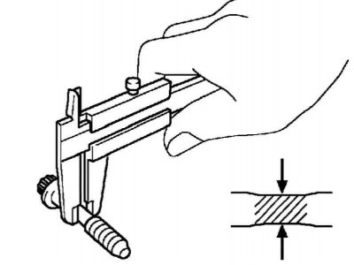
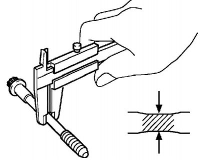
Pic. 2.294. Connecting rod measurement
Using a caliper, measure the diameter of the bolt to be extended (pic. 2.294).
- Nominal diameter: 6.6–6.7 mm.
- Minimum allowable diameter: 6.4 mm.
If the diameter is less than the minimum allowable value, the bolt must be replaced.
Checking the crankshaft
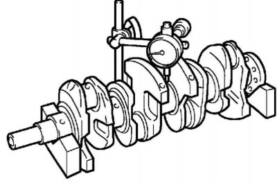
Pic. 2.295. Measuring the radial runout of the crankshaft
Establish a cranked shaft on prisms and by means of the indicator of hour type measure radial palpation, as it is shown in drawing 2.295.
- Maximum allowable radial runout: 0.03 mm.
If the radial runout exceeds the maximum allowable value, the crankshaft must be replaced.
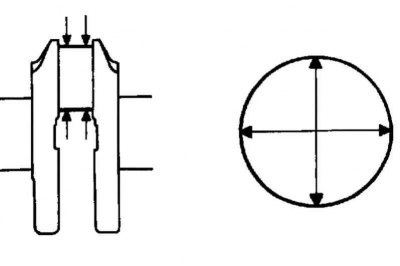
Pic. 2.296. Scheme for measuring the main journals of the crankshaft
With a micrometer, measure the diameter of all main journals at the points indicated in Figure 2.296.
- Diameter: 47.988–48.000 mm.
If the journal diameter is not as specified, check the crankshaft oil clearance.
Check the taper and ovality of all main journals, as shown in Figure 2.296.
- Maximum allowable taper and ovality: 0.02 mm.
If the taper and ovality exceed the maximum allowable value, the crankshaft must be replaced.
Pic. 2.297. Scheme for measuring the connecting rod journals of the crankshaft
Micrometer measure the diameter of all connecting rod journals at the points indicated in Figure 2.297.
- Diameter: 43.992–44.000 mm.
If the journal diameter is not as specified, check the connecting rod oil clearance.
Check the taper and ovality of all connecting rod journals, as shown in Figure 2.298.
Maximum allowable taper and ovality: 0.02 mm.
If the taper and ovality exceed the maximum allowable value, the crankshaft must be replaced.
Check of bolts of fastening of covers of main bearings of a cranked shaft
Pic. 2.298. Bolt Extension Diameter Measurement
Using a caliper, measure the diameter of the bolt to be extended (pic. 2.298).
- Nominal diameter: 7.3–7.5 mm.
- Minimum allowable diameter: 7.3 mm.
If the diameter is less than the minimum, replace the main bearing cap bolt.
Checking the crankshaft oil clearance
Clean all main journals and main bearing shells.
Note. Do not turn the crankshaft.
Install the crankshaft to the cylinder block.
Place a crushable plastic gauge along each main journal.
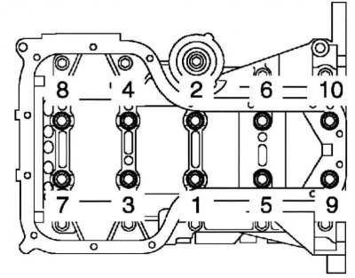
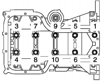
Pic. 2.299. The sequence of tightening the bolts of the main bearing block
Using SST, tighten the bolts in several steps to the prescribed torque, following the sequence shown in Figure 2.299.
- Tightening torque: 44 Nm.
Mark the front side of each of the main bearing cap bolts with paint.
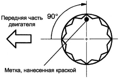
Pic. 2.300. Adjustment angle of bolts of fastening of radical bearings
Tighten the cap bolts by 90°, as shown in Figure 2.300.
Make sure the marks are rotated 90°from their original position.
Tighten the remaining 10 main bearing cap bolts.
Tightening torque: 19 Nm.
Remove 10 bolts.
Pic. 2.301. The sequence of unscrewing the bolts of the main bearing block
In several steps, evenly loosen and unscrew 10 bolts of the block of bearing caps in the sequence shown in Figure 2.301.
Measure the collapsible plastic gauges at their widest point.
- Nominal oil clearance: 0.015–0.032 mm.
- Maximum allowable oil clearance: 0.05 mm.
Note. Completely remove the remnants of crumpled plastic gauges.
If the oil clearance exceeds the maximum allowable value, replace the main bearing shells.
If necessary, replace the crankshaft.
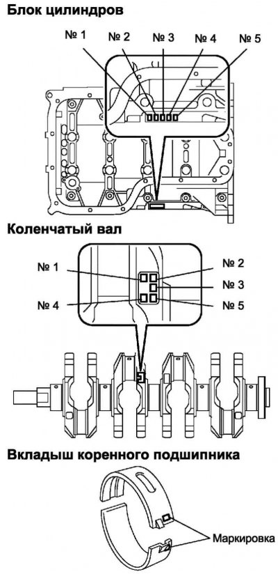
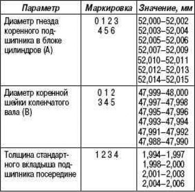
Pic. 2.302. Insert selection scheme
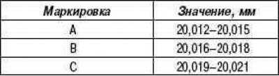
Note. The new bearing shell must be in the same size group as the old bearing. The size group number is indicated on the insert. If the number on the bearing cannot be determined, the bearing size group is selected according to the table below after adding the numbers stamped on the cylinder block and on the crankshaft. Bearing shells are supplied in 4 standard size classes, marked with numbers accordingly «1», «2», «3» and «4» (pic. 2.302).
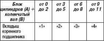
Example: cylinder block «3» (A) + crankshaft «4» (B) = sum 7 (use a bearing «3»).
Pressing in guide pins
Pic. 2.303. Scheme of pressing guide pins
Using a plastic hammer, press 9 guide pins into the cylinder block (pic. 2.303).
Rated performance
Installing guide bushings
Pic. 2.304. Scheme of pressing the guide shvtuk
Using a plastic hammer, press 5 new guide bushings into the cylinder block (pic. 2.304).
Rated performance
Stud installation
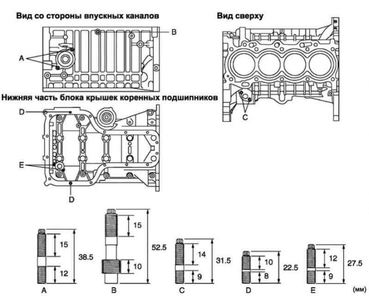
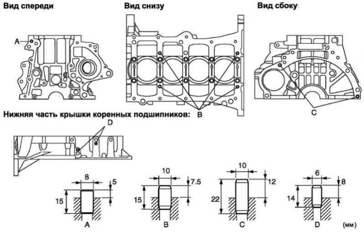
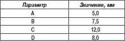
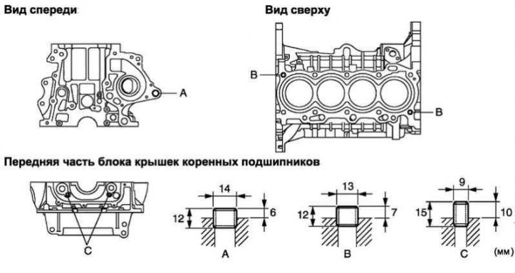
Pic. 2.305. Stud installation scheme
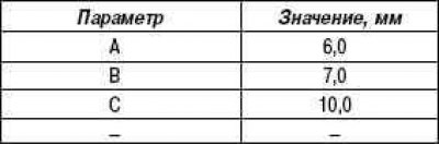
Using socket wrenches TORX E5 and E7, wrap 9 studs into the cylinder block (pic. 2.305).
Torque:
- 5.0 Nm for A;
- 11 Nm for B;
- 5.0 Nm for C;
- 5.0 Nm for D;
- 5.0 Nm for E.
Installation of the piston assembly with the piston pin
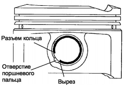
Pic. 2.306. Scheme for installing a new retaining ring
Using a small screwdriver, install a new circlip into one of the piston holes against the piston pin (pic. 2.306).
Note. Make sure the ring connector aligns with the notch in the piston.
Gradually heat the piston to a temperature of 80–90°C.
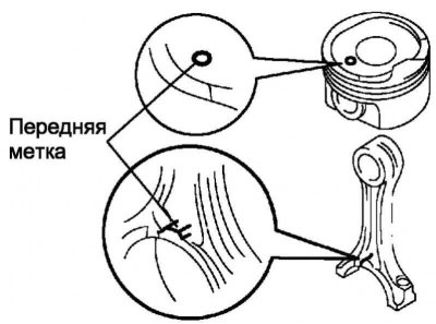
Pic. 2.307. Piston and connecting rod alignment marks
Align the front marks on the piston and connecting rod, and by hand insert the piston pin into the holes in the piston and in the upper head of the connecting rod (pic. 2.307).
Using a small screwdriver, install a new circlip into one of the piston bores against the piston pin (pic. 2.306).
Installing the piston ring kit
Install the expander and 2 sidewalls of the compound oil scraper ring by hand.
Note. When reusing piston rings, they should be installed on the same pistons from which they were removed and in the same position.
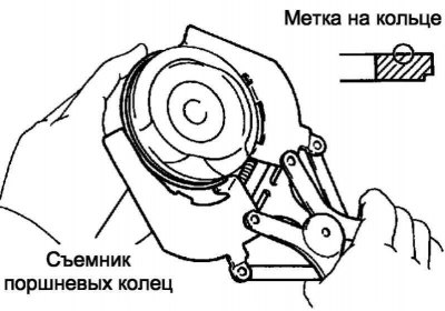
Pic. 2.308. Installation of compression rings
Install the 2 compression rings using a piston ring plier with the markings facing the piston crown (pic. 2.308).
Marking (only for compression ring no. 2): 2R.
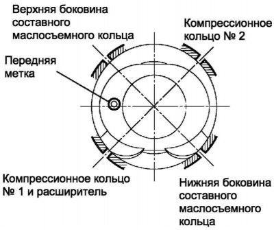
Pic. 2.309. The layout of the locks of the piston rings
Expand piston rings so that their locks were located according to drawing 2.309.
Installing the crankshaft bearing shells
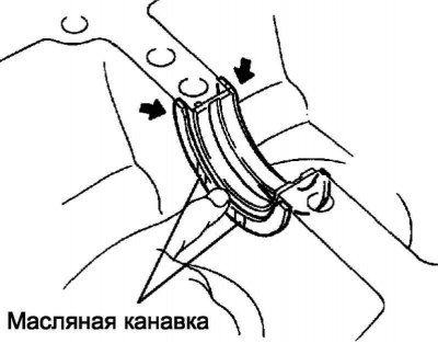
Install the upper bearing shell with oil groove into the cylinder block.
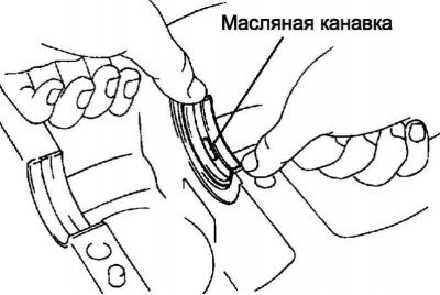
Pic. 2.310. Installing the crankshaft bearing shells
Install the lower bearing shells into the main bearing caps (pic. 2.310).
Note. Do not lubricate the bearing shells and the surface in contact with them with engine oil.
Installation of the upper thrust semi-rings of the crankshaft
Pic. 2.311. Installation of upper thrust half rings
Install the 2 top thrust washers on the #3 main journal seat in the cylinder block with the oil grooves facing out (pic. 2.311).
Installing the crankshaft
Lubricate the upper bearing shells with engine oil and install the crankshaft into the cylinder block.
Apply a light coat of engine oil to the bolt threads, bolt seats, and main bearing cap bushings.
Install the crankshaft to the cylinder block.
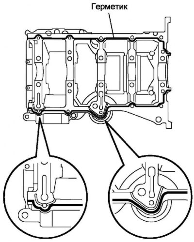
Pic. 2.312. Sealant laying scheme
Apply sealant in a continuous bead (diameter 2.5–3.5 mm), as shown in Figure 2.312.
Note. Clean the mating surface of oil.
Note. Install the main bearing cap assembly within 3 minutes of applying the sealant.
Note. Fill the engine with oil not earlier than 2 hours after installing the cover assembly.
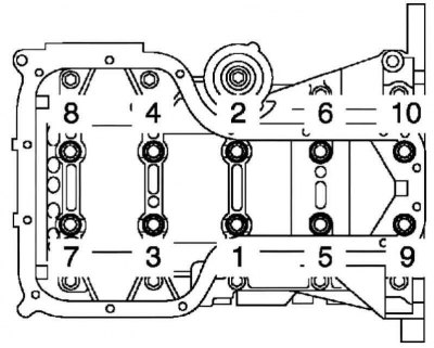
Pic. 2.313. Sequence of tightening of bolts of fastening of the block of covers of main bearings
In several steps, tighten the bolts to the prescribed torque, following the sequence shown in Figure 2.313.
- Tightening torque: 44 Nm.
Mark the front side of each of the main bearing cap bolts with paint.
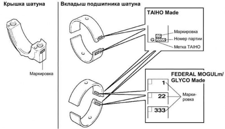
Pic. 2.263. Markings and labels on the caps of the connecting rods and on the shells of the bearings of the connecting rods
Tighten bolts of fastening of covers on 90°, as it is specified in drawing 2.263.
Make sure the marks are rotated 90°from their original position.
Tighten the remaining 10 main bearing cap bolts.
- Tightening torque: 19 Nm.
Installing connecting rod bearing shells
Align the tab on the bushing with the groove on the connecting rod cap.
Install the connecting rod bearing into the connecting rod cap.
Note. Do not lubricate the bearing shells and the surface in contact with them with engine oil.
Align the tab on the bushing with the groove on the connecting rod.
Install the bearing shell into the connecting rod.
Connecting rod assembly installation
Expand piston rings so that their locks were located according to drawing 2.309.
Lubricate the cylinder walls, pistons and surfaces of the connecting rod bearing shells with engine oil.
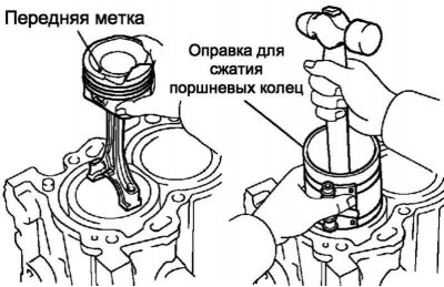
Pic. 2.314. Installing the piston with connecting rod assembly
Using a piston ring mandrel, insert the pistons with the connecting rods into the cylinders with the mark on the piston facing the front of the engine (pic. 2.314).
Align the dowel pins on the connecting rod cap with the holes in the connecting rod and install the cap.
Note. Fit the connecting rod caps to their respective connecting rods.
Make sure the tab on the connecting rod bearing cap is oriented in the correct direction.
Apply a light coat of engine oil to the threads and under the heads of the connecting rod cap bolts.
Using SST 09205-16010, tighten the bolts in several steps to the prescribed torque.
- Tightening torque: 20 Nm.
Mark the front side of each of the connecting rod cap bolts with paint.
Tighten the cover bolts by 90°.
Make sure the crankshaft rotates smoothly.
Installing the Coolant Drain Valve Assembly
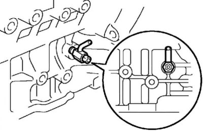
Pic. 2.315. Scheme of installation of the valve for draining the coolant assembly
Apply threadlocker to 2 or 3 threads of the coolant drain valve, then screw in the valve within 3 minutes as shown in the figure (pic. 2.315).
- Tightening torque: 25 Nm.
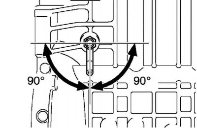
Pic. 2.316. Drain plug position
Tighten to the specified torque by turning the tap clockwise so that the drain fitting is pointing down (pic. 2.316).
Note. Fill the coolant no earlier than one hour after installing the valve.
Note. When turning the valve, it must not be turned more than 360°, and it must not be loosened after correct installation.