
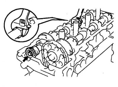
Details of the cylinder head of engines 2.4 and 2.7 l
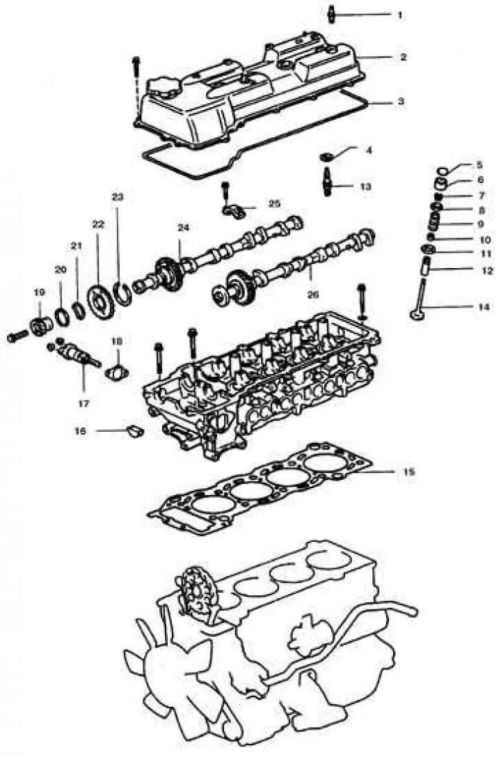
1. Crankcase ventilation spool; 2. Lid; 3, 15, 18. Gasket; 4. O-ring; 5. Adjusting washer; 6. Pusher; 7. Crackers; 8. Plate; 9. Spring; 10. Oil scraper cap; 11. Support washer; 12. Guide sleeve 13. Candle; 14. Valve; 16. Plug; 17. Tensioner; 19. Camshaft drive gear; 20. Retaining ring; 21. Spring washer; 22. Auxiliary gear; 23. Spring; 24. Exhaust camshaft; 25. Support neck cover; 26. Intake camshaft
Camshaft cover removal sequence
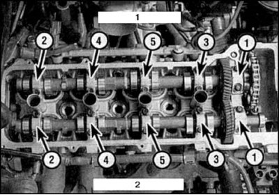
1. Intake camshaft
2. Exhaust camshaft
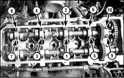
The order of tightening the bolts of the covers of the bearing necks of the intake camshaft
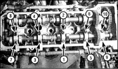
The order of tightening the bolts of the covers of the bearing necks of the exhaust camshaft
Attention! Before performing work, prepare two bolts with a thread of 6x1 mm and a length of 16–20 mm, which will be used as auxiliary during disassembly (see below).
Removing
1. Remove the cylinder head cover (see subsection 3.1.4).
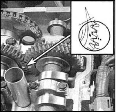
2. Set the piston of the 1st cylinder to the TDC of the compression stroke. Make sure that the dot marks on the camshaft drive and driven gears are aligned and in line with the split plane of the cylinder head and cover.
3. Otherwise, check that the TDC risk of the crankshaft is aligned with the zero division of the scale and turn the crankshaft 1 revolution.
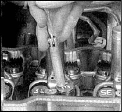
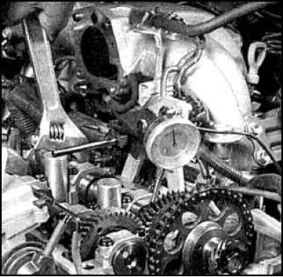
4. Measure the end play of each camshaft. To check the end play, move the camshaft back, set the indicator to zero, then move the camshaft forward. If the play exceeds the maximum allowable, then the camshaft and (or) the cylinder head must be replaced.
5. Remove the ignition distributor, if provided (see subsection 11.5).
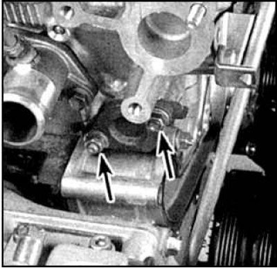
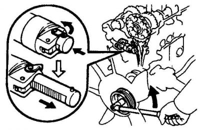
6. Loosen the chain tensioner bolts (arrows).
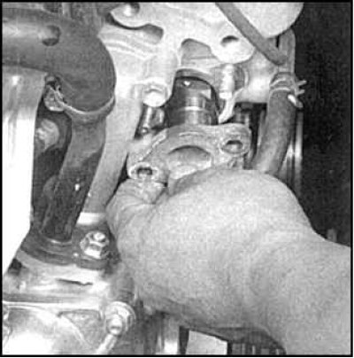
7. Remove the chain tensioner.
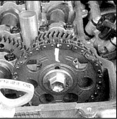
8. Label the chain link opposite the dot mark.
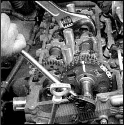
9. Loosen the sprocket bolt while holding the camshaft with a wrench. Remove the distributor drive gear.
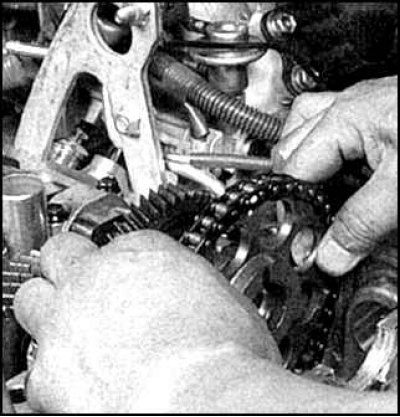
10. Carefully remove the sprocket and chain from the camshaft and leave them on the chain guides.
Exhaust camshaft
11. First, remove the exhaust camshaft after fixing the auxiliary gear spring.
Attention! Remove the camshafts one by one, keeping them parallel to the plane of the cylinder head. Otherwise, the cylinder head may be damaged.
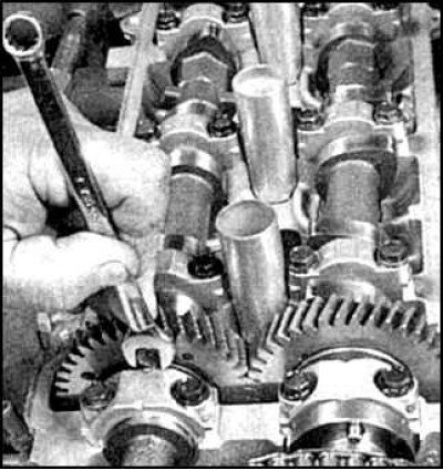
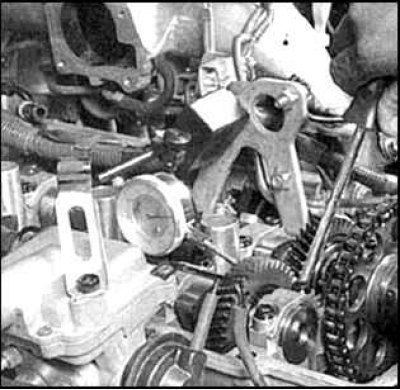
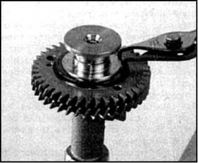
12. To fix the spring, turn the camshaft so that the service hole for the auxiliary bolt is facing vertically upwards.
13. Attach the auxiliary gear to the main gear with a pre-prepared bolt with an M6 thread and a length of 15–20 mm.
14. On engines up to 1998, unscrew the bolt and remove the distributor gear.
15. Move the camshaft back, gradually and evenly unscrew the bolts of the cover of the necks of the camshaft N1 (see fig. Camshaft cover removal sequence).
16. Carefully unscrew the bolts of the remaining camshaft journals, making sure that the camshaft rises evenly. If the camshaft comes out skewed, tighten the cover bolts N3 and, supporting the camshaft by the gear, gradually loosen the bolts.
Intake camshaft
17. Move the camshaft forward, gradually and evenly unscrew the bolts of the cover of the camshaft journals N1 (see fig. Camshaft cover removal sequence).
18. Carefully unscrew the bolts of the remaining camshaft journals, making sure that the camshaft rises evenly. If the camshaft is released with a warp, then wrap the bolts of the middle cover (N3) and, supporting the camshaft by the gear, gradually loosen the bolts.
19. Remove the intake camshaft.
20. Wipe the adjusting washers of the pushers from the oil, mark with a marker and remove the pushers and adjusting washers.
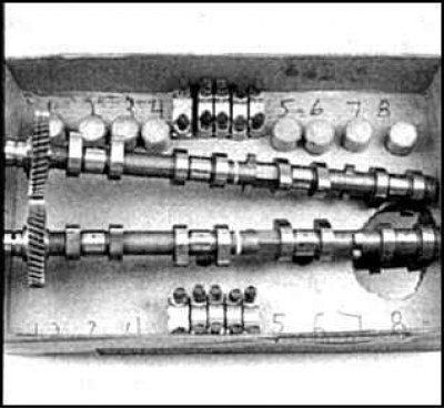
21. Store bearing caps, pushrods and washers in the order in which these parts were installed.
Examination
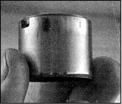
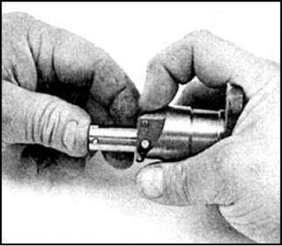
1. Clamp the intake camshaft in a vice with soft jaws on the hex neck.
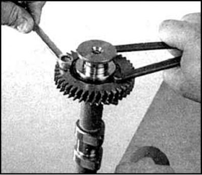
2. Using a wrench with two thrust pins, turn the secondary gear clockwise, then unscrew the auxiliary bolt securing the main and auxiliary gears, and carefully loosen the force, allowing the auxiliary gear to turn counterclockwise until the spring is completely released.
3. Remove the sub gear circlip.
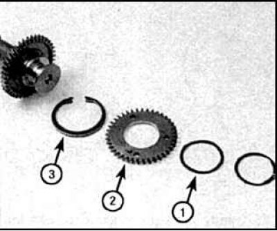
4. Remove spring washer (1), auxiliary gear (2) and auxiliary gear spring (3).
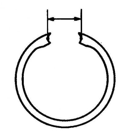
5. Measure the distance between the ends of the auxiliary gear spring in the free state and compare with the standard. If the distance differs from the standard, then replace the spring.
6. Check up a condition of pushers. The presence of chips and deep development is not allowed.
7. Check for signs of wear on the bearing journals and camshaft cams - grooves, pits, metal enveloping and signs of overheating (areas of bluish color, or colored areas). Check each cam for delamination of the hardened layer.
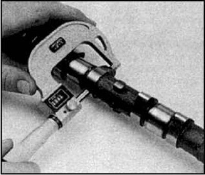
8. Measure the size of each camshaft cam and compare with the standard. If the size of at least one cam is less than the standard, then replace the camshaft.
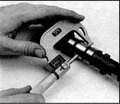
9. Measure the diameter of the camshaft bearing journals and compare with the standard. If the diameter of at least one bearing neck is less than the standard, then replace the camshaft.
10. Check the bearing journal clearances for each camshaft by proceeding as follows.
11. Clean the camshaft bearing journals and bearing journal covers in solvent.
12. Place the camshaft carefully (s) into the cylinder head without pushers, shims and auxiliary gear. The presence of oil on the necks is not allowed.
13. Lay pieces of plastic gauge wire across each camshaft bearing journal.
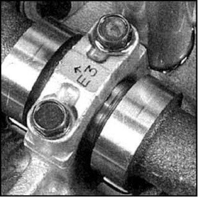
14. Install the camshaft bearing journals with the arrows pointing towards the toothed belt.
15. Tighten the bolts to the specified torque by turning each bolt 1/4 turn at a time.
Attention! Turning the camshaft with the plastic gauge inserted is not permitted.
16. Turn away bolts and remove covers.
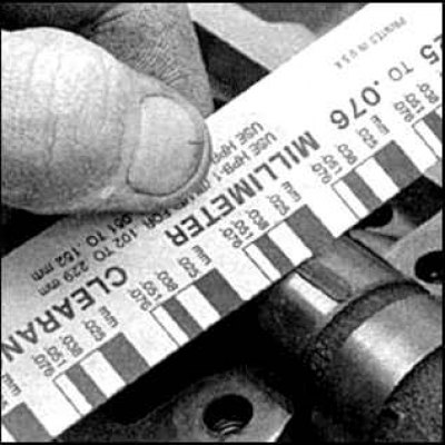
17. Compare the crushed wire width (at the widest point) with a scale on the package.
18. If the clearance in at least one of the necks exceeds the norm, then the camshaft and (or) the cylinder head must be replaced.
19. Use your fingernail or credit card to scrape off any remaining plastic, being careful not to scratch the support neck or the inside of the lid.
20. With the bearing journal covers temporarily installed, check the clearance in the meshing of the camshaft gears. Holding one of the camshafts by the hex neck with a wrench, check the amount of movement of the gear of the other camshaft. Compare the result with the standard. If the clearance is higher than normal, replace both camshafts.
Installation
Intake camshaft
1. Lubricate and install the pushers and shims in their original places, having previously lubricated with molybdenum grease.
2. Upper bolts securing the clutch housing to the cylinder block.
3. Lubricate the bearing journals and camshaft cams with molybdenum grease. Lubricate the thrust portion of the intake camshaft.
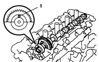
4. Install the intake camshaft into the cylinder head so that the dowel pin (1) was facing up.
5. Move the camshaft forward and install the bearing journal covers in their original places, observing the numbering and orientation of the arrows, which should be directed towards the toothed belt.
6. Pull up in sequence (see fig. The order of tightening the bolts of the covers of the bearing necks of the intake camshaft), the cover bolts until they come into contact with the cylinder head. Do not completely tighten the bolts.
7. Tighten all bolts to the specified torque.
Exhaust camshaft
8. Assemble exhaust camshaft with springs and auxiliary gear, secure all parts with circlip.
9. Lubricate and install the pushers and shims in their original places, having previously lubricated with molybdenum grease.
10. Lubricate the bearing journals and camshaft cams with molybdenum grease.
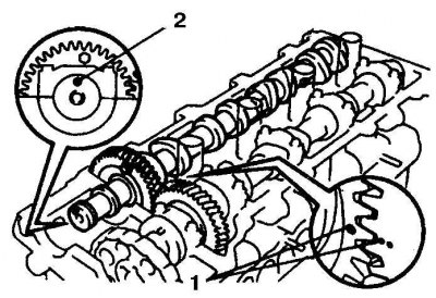
11. Align marks (2) on the camshaft gears. locating pin (1) exhaust camshaft must face up.
12. It should be borne in mind that the gas distribution design of the engine in question does not allow for traction connections. The cap bolts should be tightened in this position, after which the camshaft should be rotated back to set to the TDC position, in which the contact surfaces are in contact evenly, without obstacles from the forces of the springs acting on the cams.
13. Rotate the exhaust camshaft over the intake camshaft and reinstall. Rotate the camshaft in both directions to ensure proper seating in the bearings.
14. Move the camshaft forward and install the bearing journal covers in their original places, observing the numbering and orientation of the arrows, which should be directed towards the toothed belt.
15. Tighten, following the sequence, the bolts of the covers until they come into contact with the cylinder head (see fig. The order of tightening the bolts of the covers of the bearing necks of the exhaust camshaft). Do not completely tighten the bolts.
16. Tighten all bolts to the specified torque in several stages.
17. Turn the camshafts so that the auxiliary bolt is at the top and remove the bolt. Check for smooth rotation of the camshafts.

18. Align the marks on the gears. Make sure the TDC mark of the crankshaft pulley is aligned with TDC.

19. Install the sprocket chain, making sure the marks match.
20. Put on the distributor gear, tighten the bolt.
21. Pull out the tensioner safety catch and push the plunger in.

22. Secure the plunger by putting on the hook.
23. Rotate the crankshaft until the hook comes off the plunger pin.
24. If the plunger does not come out, press the tensioner shoe and release the plunger hook.
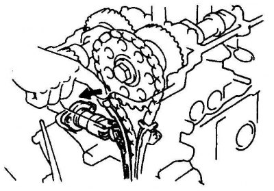
25. Install the tensioner, replacing the gasket.
26. Further installation is carried out in the reverse order. Adjust valves and ignition timing if necessary (see subsection 11.6).