
Details of the front of the engine
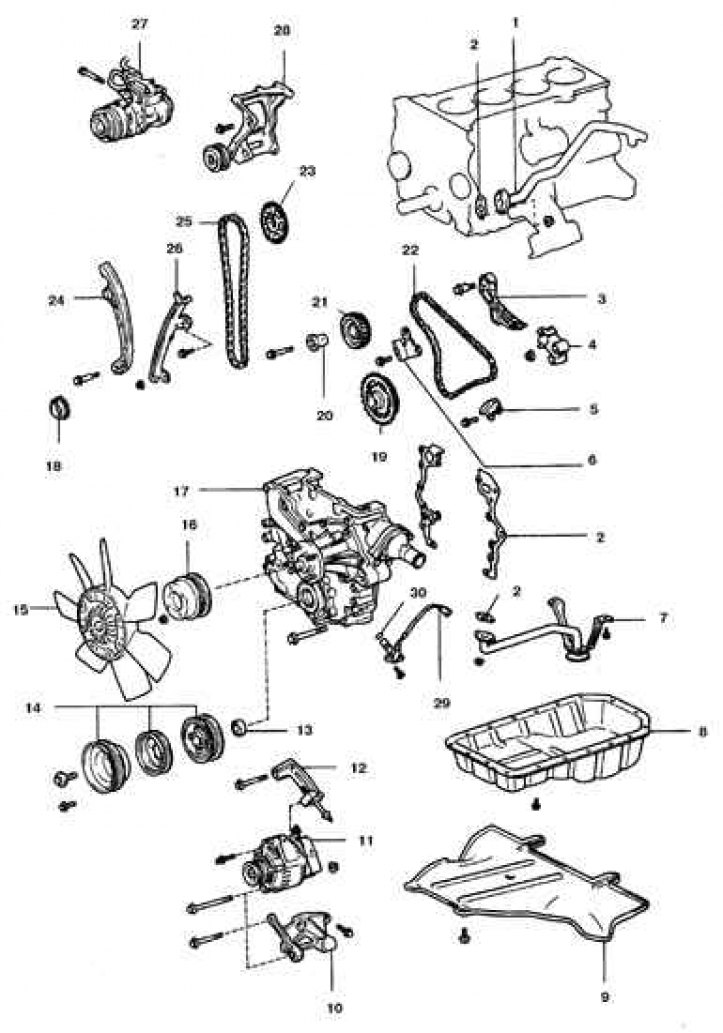
1. Coolant bypass pipe N1; 2. Gasket; 3. Calm N2; 4. Tensioner N2; 5. Calm N3; 6. Calm N4; 7. Oil receiver; 8. Pallet; 9. Shield; 10. Bracket; 11. Generator; 12. Adjustment bracket; 13. Oil seal; 14. Pulley; 15. Impeller with hydraulic drive; 16. Coolant pump pulley; 17. Chain cover; 18. Camshaft chain drive gear; 19. Crankshaft drive sprocket N2; 20. Roller of the drive gear of the balancing shaft; 21. Balance shaft drive gear; 22. Balance shaft chain; 23. Camshaft sprocket; 24. Tensioner shoe; 25. Camshaft chain; 26. Calm N1; 27. Compressor; 28. Bracket; 29. Crankshaft rotation sensor; 30. O-ring
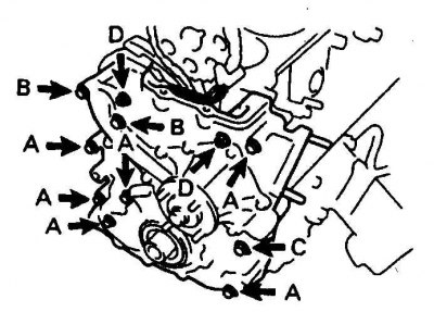
Designation of different sizes of chain cover bolts
Removing
1. Disconnect the battery from the ground.
2. Drain the oil and coolant.
3. Raise the front of the car.
4. Remove the bottom shields.
5. Remove the radiator expansion tank.
6. Turn out candles and remove all belts of a drive.
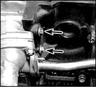
7. Loosen the bolts (indicated by arrows), remove the air conditioning compressor and take it to the side without disconnecting it from the highway.
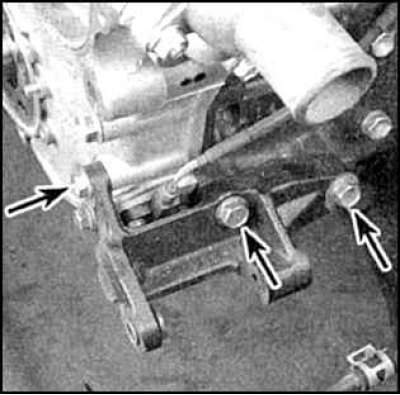
8. Remove alternator, tensioner pulley and bracket (bottom bracket bolts are indicated by arrows).
9. Remove the cruise control actuator (if provided).
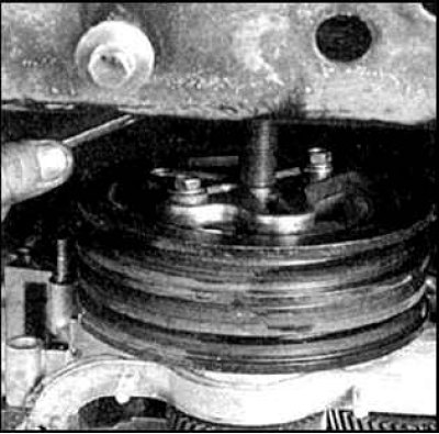
10. Disconnect the lower radiator hose and remove the coolant pump.
11. Set the piston of the 1st cylinder to the TDC of the compression stroke.
12. Remove the cylinder head.
13. Remove the tray.
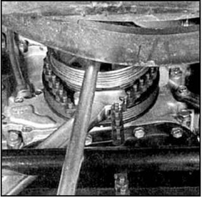
14. Lock the crankshaft pulley to loosen the bolt.
15. Loosen the bolt and remove the crankshaft pulley.
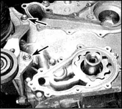
16. Turn away bolts (arrows) and chain cover nuts.
17. Remove the cover carefully.
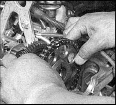
18. Remove chain and sprocket.
19. Remove dampers and tensioner parts.
Examination
1. Check the condition of the chain and dampers. Replace worn parts. In case of severe wear of dampers, remove and clean the sump and oil receiver.
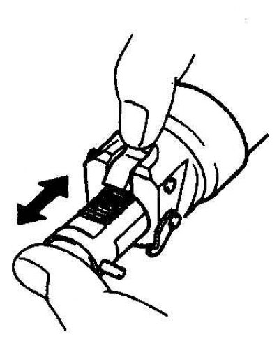
2. Check plunger operation. The plunger should move freely with the latch retracted.
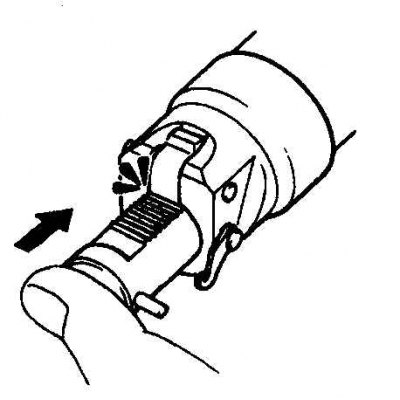
3. Check the operation of the tensioner. The retainer must securely hold the plunger.
4. Check the cleanliness of the oil nozzle jet.
Installation
1. Clean the front of the engine, chain and cover, install the injector. The nozzle must face the chain.
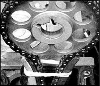
2. Fit the chain to the camshaft sprocket, lining up the links with the identification marks on the drive and driven sprocket. Crimp the chain by tying it with a strong tape.
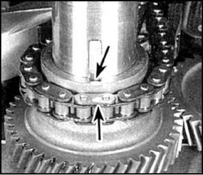
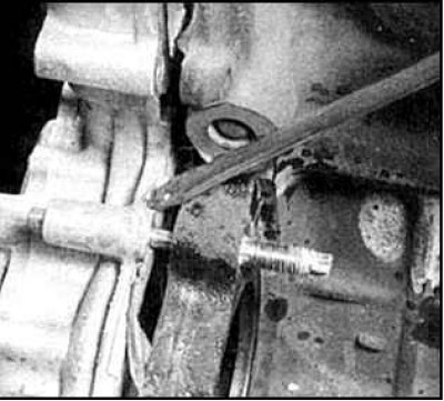
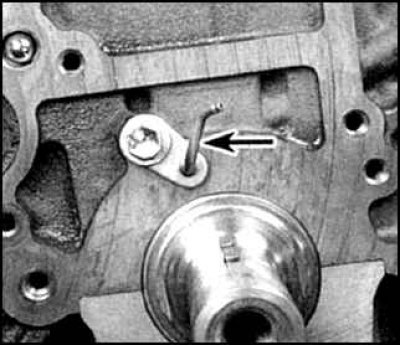
3. Align the link with the ID mark (indicated by an arrow) with groove for crankshaft key (indicated by an arrow) and put on the leading sprocket.
4. Apply a bead of sealant to the cover, make sure all gaskets are present and install the cover (within 5 minutes after application), by engaging the oil pump drive rotor shaft with the crankshaft drive gear.
5. Install bolts and tighten to specified torque (see subsection 3.1.1). The bolts of fastening of a cover of a chain differing in the sizes are specified on fig. Designation of different sizes of chain cover bolts. Remove the chain tie.
6. Install the rest of the parts in reverse order. Make sure the cover is installed correctly, fill the cooling system with liquid, fill in oil. Start the engine, check for leaks. Set the ignition timing and test the driving performance of the vehicle.