
Company Honda Company Ford Company Skoda Company Kia Company Mazda Company Mercedes Company Renault
English Русский
Български
Беларускі
Український
Српски
Hrvatski
Română
Polski
Slovenský
Magyar
Bookmark Articles Sitemap Contacts
ToyotaMan.ru


Camry Corolla Corona Carina Land Cruiser Highlander 4Runner RAV4 Others
RAV 4 XA20 (2000-2005) RAV 4 XA10 (1994-2000)

Fuel tank — removal and installation [Toyota RAV4 XA10]

  • Main
  • RAV4
  • XA10 (1994-2000)
  • Power unit
  • Fuel and exhaust system
  • Fuel tank — removal and installation
0
Remove the fuel tank as follows.

Relieve pressure in the fuel system.

Remove the fuel filler cap from the fuel tank, which will equalize the pressure in the fuel tank with atmospheric pressure.

Turn off the ignition and disconnect the ground wire from the battery.

If there is fuel in the fuel tank, pump it out. Pump out the fuel using a special pump.

Raise the car on a lift.

Remove the rear and center sections of the exhaust system.

On all-wheel drive vehicles, remove the driveshaft.

(The original version is published on the website: www.TOYOTAMAN.ru)
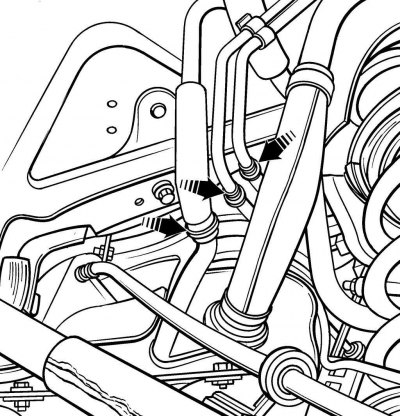


Figure 5.16. Connection points of fuel lines and fuel vapor return pipe to the fuel tank


Disconnect the fuel lines, fuel vapor return tube and filler neck from the fuel tank (figure 5.16). Close the fuel lines with plastic plugs to prevent fuel leakage and contamination of the fuel system.

Support the fuel tank with a jack and a wooden block.


Figure 5.17. Location of fuel tank support strap mounting bolts
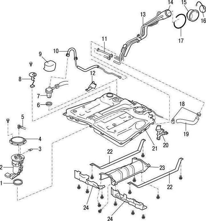


Figure 5.18. Fuel tank of vehicles manufactured before 2001: 1 – gasket; 2 – fuel pump/fuel level sensor unit; 3 – tube fastening clamp; 4 – fuel tank cap; 5 – gasket; 6 – main fuel tank pipe; 7 – filling control valve; 8 – fuel level sensor; 9 – protective cover of the filling control valve; 10 – thick fuel pipe; 11 – air removal tube; 12 – protective plate; 13 – tube; 14 – filler neck; 15 – filler neck; 16 – filler cap; 17 – retaining ring; 18 – clamps; 19 – fuel inlet hose; 20 – protective plate; 21 – fuel tank; 22 – fuel tank support band; 23 – protective plate; 24 – protective plates


Remove the fuel tank support strap mounting bolts (figure 5.17, 5.18).

Lower the fuel tank enough to allow the electrical connector to be disconnected from the fuel pump/fuel level sensor assembly.

Remove the fuel tank from under the vehicle.

Warning! Even an empty fuel tank contains fuel vapors that are explosive, so use caution.


Any repair to the fuel tank or filler neck should be performed by a professional who is experienced in performing critical and potentially hazardous work. Even after cleaning and flushing the fuel tank, it still contains explosive fuel vapors.


Later production vehicles are equipped with fuel tanks made of plastic, which cannot be repaired.

The removed fuel tank must be located away from open flames, sparking devices, open fire-hazardous lighting devices and smoking areas.

Install the fuel tank in the reverse order of removal.
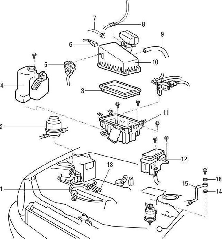


Figure 5.19. Air filter on models before 2001: 1 – accelerator cable; 2 – power steering hydraulic system reservoir; 3 – air filter element; 4 – expansion tank; 5 – slip control relay; 6 – electrical connector for the engine air temperature sensor; 7 – Positive crankcase ventilation (PCV) hose; 8 – high-voltage wires; 9 – air hose; 10 – air filter cover; 11 – air filter housing; 12 – relay block No. 2; 13 – throttle control cable; 14 – gasket; 15 – fuel supply pipe; 16 – gasket
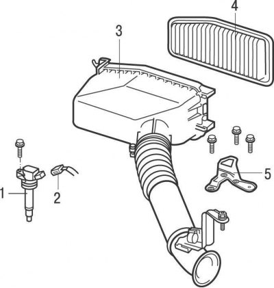


Figure 5.20. Air filter on models since 2001: 1 – ignition coil; 2 – ignition coil electrical connector; 3 – air filter housing; 4 – air filter element; 5 – air filter bracket


Remove and install the air filter housing as follows: (figures 5.19 and 5.20):

Release the spring clips and remove the air cleaner cover and element.

On pre-2001 models, disconnect the electrical connector from the slip control relay located on the side of the air cleaner cover.

On 2001 and later models, disconnect the air intake hose from the air cleaner cover.
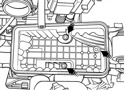


Figure 5.21. Location of air filter housing mounting screws


Remove 3 screws and remove the air filter housing (figure 5.21).

Install the air filter housing in the reverse order of removal.

Install the air filter housing in the reverse order of removal.
This article is available at: russian, bulgarian, belarusian, ukrainian, serbian, croatian, romanian, polish, slovak, hungarian
The article material has been checked: Kolokoltsev Grigory
Share information:
◀ Previous
RAV 4 XA10: Fuel and exhaust system
Next ▶

Fuel level sensor — removal and installation
Fuel pressure regulator — removal and installation
Fuel pump — removal and installation
Checking fuel lines, hoses and their connections
Checking the fuel pump
Air filter housing
Accelerator cable — removal and installation
Electronic fuel injection system — general information
Checking the electronic fuel injection system
Diagnostics of the Toyota TCCS electronic fuel injection system with…
Similar articles on other Toyota models

➥ Fuel tank cap Toyota Camry XV20 (1996-2001)
➥ Fuel tank cap release lever Toyota Corolla E80 (1983-1990)
➥ Fuel tank and fuel lines Toyota Corona T190 (1992-1997)
➥ Removal and installation the fuel tank Toyota Carina T190 (1992-1996)
➥ Fuel tank — removal and installation Toyota Cruiser 60/80 (1980-1997, petrol)
➥ Fuel Tank Cleaning and Repair — General Information Toyota Highlander 1 (2000-2007, petrol)
Link in different formats to this article
Comments and feedback from visitors
No comments yet


Add two numbers 45 + 38


RAV 4 XA20 (2000-2005) 
  • General information
  • Introduction to manual
  • User manual
  • Daily care
  • Maintenance (petrol)
  • Maintenance (diesel)
  • Troubleshooting
  • Power unit
  • Gasoline engines (before 2000)
  • Petrol engines (since 2001)
  • Diesel engines
  • Engine overhaul
  • Cooling and heating
  • Fuel system (petrol)
  • Fuel system (diesel)
  • Engine electrical equipment
  • Control system (petrol)
  • Control system (diesel)
  • Transmission
  • Manual gearbox
  • Automatic gearbox
  • Clutch and drive shafts
  • Chassis, running gear
  • Brake system
  • Front suspension
  • Rear suspension
  • Steering system
  • Body and interior
  • Exterior (external elements)
  • Interior (internal elements)
  • Doors, locks and windows
  • Electrical equipment
  • Equipment and devices
  • Electrical circuits
RAV 4 XA10 (1994-2000) 
  • General information
  • User manual
  • Maintenance
  • Power unit
  • Petrol engine 3S-FE
  • Petrol engine 1AZ-FE
  • Engine overhaul
  • Cooling and air conditioning
  • Fuel and exhaust system
  • Ignition system
  • Toxicity reduction system
  • Transmission
  • Clutch
  • Mechanical gearbox
  • Automatic gearbox
  • Cardan and drive shafts
  • Chassis, running gear
  • Brake system
  • Car suspension
  • Steering
  • Body and interior
  • Exterior (external elements)
  • Interior (internal elements)
  • Doors, locks and windows
  • Electrical equipment
  • Equipment and devices
  • Power devices
  • Electrical circuits
ToyotaMan.ru © 2018–2026 • Mobile version • Interesting about Toyota • Administration • Sitemap: EN BG BY UA RS HR RO PL SK HU • Search system • Bookmark
Camry Vista-V40 • Camry XV10 • Camry XV20 • Camry XV30 • Corolla Verso-AR10 • Corolla E80 • Corona T190 • Carina T170 • Carina T190 • Land Cruiser J70 (diesel) • Land Cruiser J60 (petrol) • Land Cruiser J100 • Highlander XU20 (petrol) • 4Runner N120 • RAV4 XA10 • RAV4 XA20 • Duet M100 • Dyna Y50 •
We require cookies to enable some interactive features. Is that ok with you?