



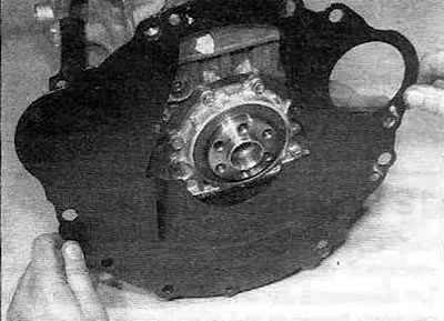
Figure 13.1,a. Remove the rear engine cover (where is it installed)...
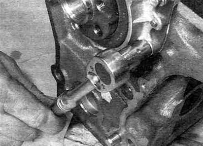
Figure 13.1, b....then unscrew the mounting bolts...
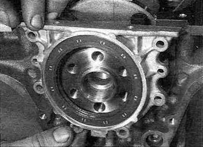
13.1, in.... remove the crankshaft oil seal housing...
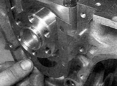
Figure 13.1, d....and remove the gasket (engines produced before 2000).
2. Remove the pistons together with the connecting rods as described in paragraph 12.
Note: If you do not plan to work on the pistons and connecting rods, there is no need to remove the head. Simply remove the caps and push the pistons upwards enough to clear the connecting rods from the crankshaft journals (without pressing the pistons against the valves).
3. Before removing the crankshaft, check its axial clearance by inserting the measuring tip of a dial indicator into the end of the crankshaft (see Figure 13.3).
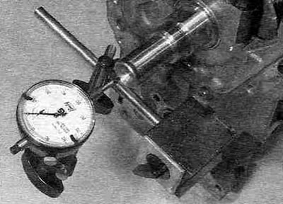
Figure 13.3. Checking the crankshaft axial clearance using a dial indicator.
4. After moving the crankshaft in the axial direction until it stops, reset the indicator, then move the crankshaft in the opposite direction and read the axial clearance values from the indicator. If the results obtained exceed the Specifications, check the crankshaft thrust faces for wear. If there are no signs of wear, adjust the crankshaft axial clearance by selecting thrust half rings of the appropriate thickness.
5. If there is no indicator, use a set of flat feeler gauges, installing them in the gap between the crankshaft and main bearing No. 3, moving the crankshaft until it stops in the axial direction (see Figure 13.5).
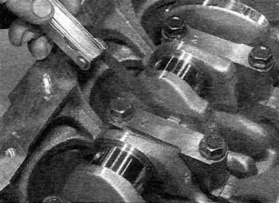
Figure 13.5. Checking the crankshaft axial clearance using a set of flat feeler gauges in the central (No. 3) main bearing.
All engines except 1.8L petrol
6. Proceed in the sequence shown in the figure 13.6,a, gradually loosen the crankshaft main bearing cap bolts.
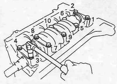
Figure 13.6,a. Sequence for loosening the main bearing cap bolts.
After loosening the tightening, unscrew the bolts. Please note that the numbering of the covers starts from the timing belt side and the arrows should also point towards the timing belt (see Figure 13.6,b).
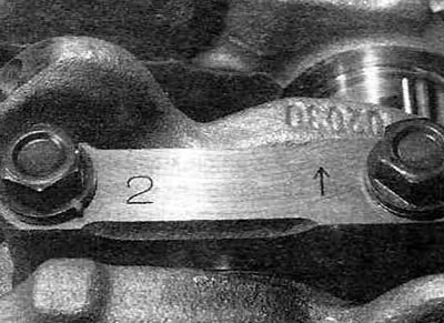
Figure 13.6, b. The main bearing caps are stamped with numbers and arrows that should point towards the engine timing drive.
If the identification marks are not visible, mark the lids in a reliable and convenient way to prevent possible assembly errors. Please note that on engines produced since 2001, all main bearing cap bolts must be replaced as a set during assembly.
7. Remove the main bearing caps and take out the lower bearing shells. Use tape to attach each insert to its own lid so they don't get mixed up or lost. Remove the thrust washers from each side of the central main bearing cap, having first marked their location.
8. Carefully remove the crankshaft, being careful not to touch the upper main bearing shells.
9. Remove the upper bearing shells from the cylinder block and tape them to the corresponding main bearing caps. Also remove the thrust washers from each side of the center main bearing and place them together with the caps.
1.8L petrol engines
10. Working in a diagonal sequence, gradually and evenly loosen and then remove the ten hex head bolts securing the main bearing cap assembly (ladder) to the cylinder block (see Figure 13.10).
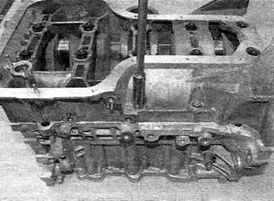
Figure 13.10. Unscrewing the mounting bolts (with hex heads) block of support caps ("ladders") to the cylinder block - 1.8 l petrol engines.
Please note that you will need to remove the oil filter nipple to gain access to one of the bolts located underneath.
11. Proceeding in reverse order to the tightening sequence (see figure 19.19) sequence, gradually and evenly release and then unscrew the ten central twelve-sided head bolts securing the "ladder" to the cylinder block (see Figure 13.11).
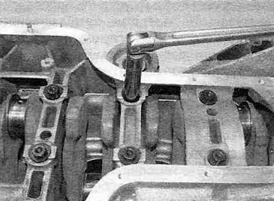
Figure 13.11. Unscrewing the mounting bolts (with twelve-sided heads) block of support caps ("ladders") to the cylinder block of 1.8 l petrol engines.
Please note that during assembly, all twelve-point head mounting bolts must be replaced as a set.
12. Using a suitable flat-blade screwdriver, carefully pry the "ladder" away from the cylinder block, resting against the specially provided lugs. Make sure that the lower liners remain in their places in the "ladder".
13. Carefully remove the crankshaft, being careful not to move the upper bearings. Remove the oil seal from the crankshaft.
14. Remove the upper main bearing shells from the cylinder block and tape them to their corresponding locations in the ladder frame. Remove the thrust washers from the center main bearing and place them together with the ladder frame.