



Contents: Removal the steering wheel assembly ↓ Removal the lower steering column…↓ Removal the steering column cover…↓ Removal the soundproofing pad of the…↓ Removal the steering column assembly ↓ Removal the steering shaft spline…↓ Removal the steering lock drive…↓ Installing the steering lock drive…↓ Installing intermediate shaft #2 of…↓ Installing the splined steering…↓ Installing the steering column…↓
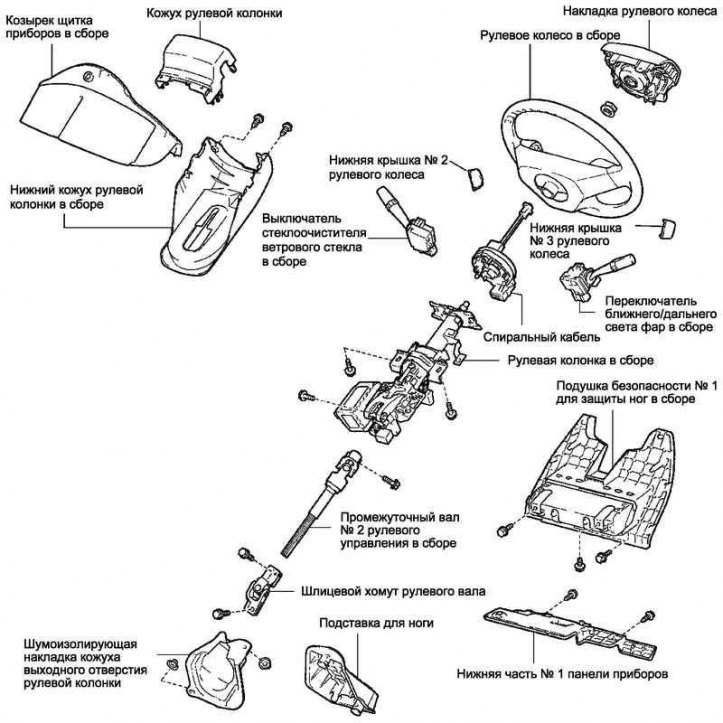
Fig. 5.21. Steering gear parts
The steering gear parts are shown in Fig. 5.21 on page 263.
Remove the steering wheel cover.
Removal the steering wheel assembly
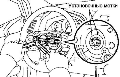
Fig. 5.22. Unscrewing the steering wheel mounting nut
Unscrew the steering wheel mounting nut (Fig. 5.22).
Mark the relative position of the steering wheel and steering shaft.
Using SST, remove the steering wheel assembly.
Remove the lower part #1 of the instrument panel.
Remove the leg airbag assembly No.1.
Removal the lower steering column cover
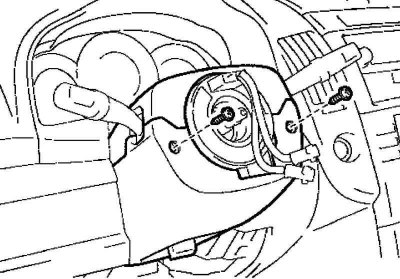
Fig. 5.23. Steering column lower cover mounting screws
Remove the two screws and remove the lower steering column cover (Fig. 5.23).
Remove the headlight low/high beam switch.
Remove the windshield wiper switch.
Removal the steering column cover together with the instrument panel visor
Disconnect the clamp and remove the steering column cover with the instrument panel visor.
Remove the coil cable.
Removal the soundproofing pad of the steering column outlet casing
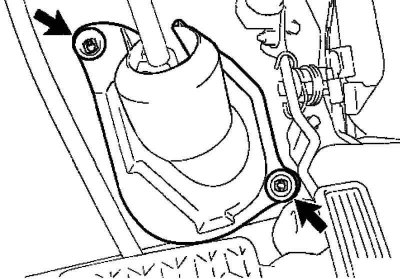
Fig. 5.24. Fastening the soundproofing pad
Remove the mat, take out the two clips and remove the soundproofing pad (Fig. 5.24).
Removal the steering column assembly
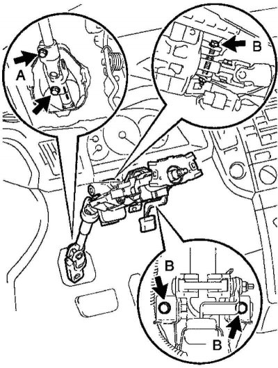
Fig. 5.25. Connectors and clamps for fastening the wiring harnesses of the steering column assembly
Disconnect the connectors and harness clamps from the steering column assembly (Fig. 5.25).
Loosen bolt A.
Loosen the three B bolts securing the steering column.
Mark the relative positions of the splined clamp of the steering shaft and the intermediate steering shaft.
Remove the bolt and disconnect the spline clamp and the intermediate steering shaft.
Remove the three bolts and remove the steering column assembly.
Removal the steering shaft spline clamp
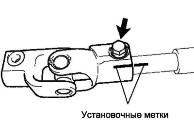
Fig. 5.26. Marks of the relative position of the spline clamp of the steering shaft and intermediate shaft No.2 of the steering control
Mark the relative position of the splined clamp of the steering shaft and intermediate shaft No.2 of the steering control (Fig. 5.26).
Loosen the bolt and remove the steering shaft spline clamp.
Removing intermediate shaft No.2 of the steering gear
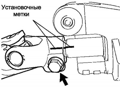
Fig. 5.27. Marks of the relative position of intermediate shaft No.2 and the main steering shaft
Mark the relative positions of intermediate shaft No.2 and the main steering shaft (Fig. 5.27).
Loosen the bolt and remove intermediate shaft No.2 of the steering gear.
Removal the steering lock drive assembly
Use a center punch to mark the centers of the two mounting bolts.
Drill out two bolts using a 3-4 mm drill bit.
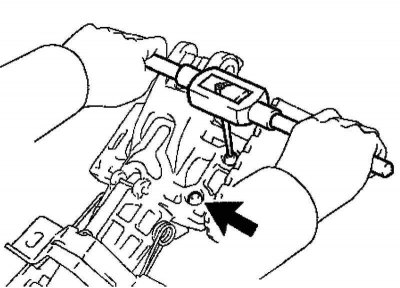
Fig. 5.28. Removing the steering lock drive mounting bolts
Using a screw puller, remove the two bolts and remove the steering lock drive (Fig. 5.28).
Installing the steering lock drive assembly
Loosely install the steering column assembly and steering lock actuator using two new bolts.
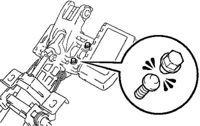
Fig. 5.29. Bolt heads
Tighten both bolts until the bolt heads break off (Fig. 5.29).
Installing intermediate shaft #2 of the steering gear
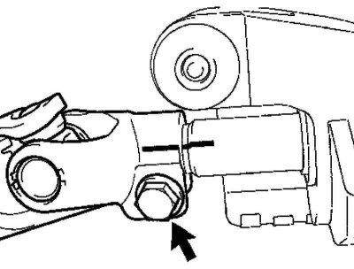
Fig. 5.30. Alignment of installation marks
Align the timing marks on intermediate shaft No.2 and the main steering shaft (Fig. 5.30).
Secure the intermediate shaft No.2 of the steering gear with a bolt.
Tightening torque: 28 Nm.
Installing the splined steering shaft clamp
Align the timing marks on intermediate shaft #2 and the splined clamp.
Tighten the spline clamp mounting bolt without tightening it.
Installing the steering column assembly
Loosen the three steering column bolts without tightening them.
Align the timing marks on the intermediate shaft and splined clamp.
Secure the spline clamp with a bolt.
Tightening torque: 35.3 Nm.
Tighten the steering column mounting bolt.
Tightening torque: 21 Nm.
Tighten bolt A.
Tightening torque: 35.3 Nm.
Connect all connectors.
Connect the wire harness clamps to the steering column.
Install the steering wheel cover.
Connect the negative battery terminal.
Check the SRS warning light.