- A) Type and adjustment of bench nozzles.
- Type of control nozzles of the fuel stand - DN12SD12 (NIPPONDENSO).
- The pressure of the beginning of the lifting of the nozzle needle is 145-155 bar.
- b) Check the stand tachometer error. Maximum permissible error±40 rpm
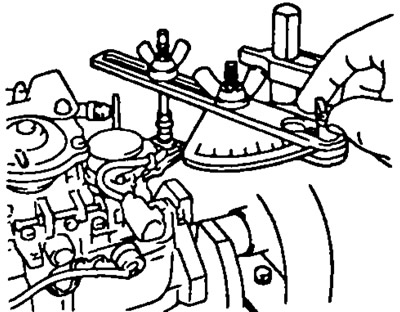
- V) Install the injection timing sensor.
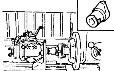
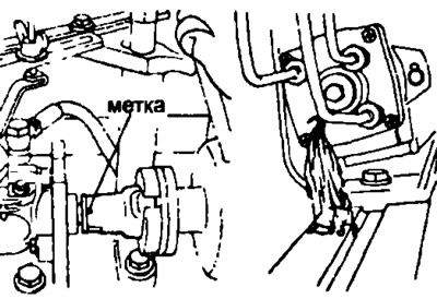
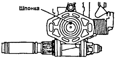
- G) Mount the injection pump on the stand.
Note: Mark the coupler against the pump shaft key.
- d) Install high pressure fuel lines with the following specifications:
- Outer Diameter: 6.0mm
- Inner Diameter: 2.0mm
- Length: 840 mm
- Minimum allowable bending radius over: 25 mm
- Tightening torque: 22 Nm
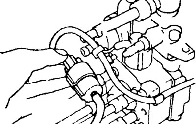
- e) Unscrew the nipple bolt of the fuel supply pipe.
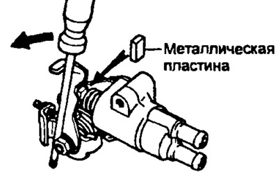
- and) After unscrewing the two bolts, remove the right cover of the automatic injection advance
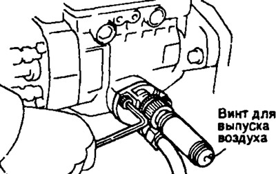
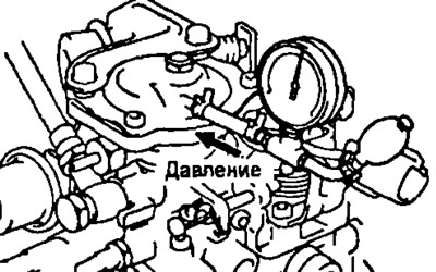
- h) Install a pressure gauge that measures the internal pressure in the injection pump housings and a device for measuring the plunger stroke. Tightening torque: 8 Nm.
Note: bleed air using the air bleed screw.
- And) (2S-T) Connect a pressure gauge to the boost corrector.
- To) Connect the wire to the supply cutoff solenoid valve terminal and apply 12V.
Note:
- The battery should be located as far as possible from the injection pump to avoid "overshoots" sparks.
- Connect the wire to the solenoid valve terminal first.
- l) The pressure in the fuel supply pipe must be 0.2 kg/cm2. Fuel temperature should be 40-45°C
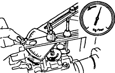
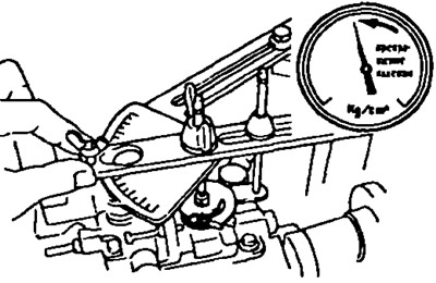
- m) Install the protractor on the fuel stand and connect it to the injection pump control lever.
- n) Lock the top of the control lever to the maximum feed position.

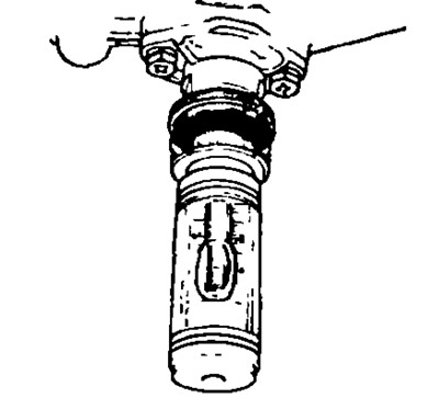
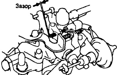
- O) Check cam washer installation.
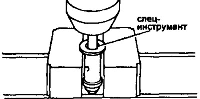
(1) Disconnect the high pressure fuel pipe from the injection fitting marked «WITH», applied on the distribution head of the injection pump.
(2) Using a special tool, unscrew the case (union) discharge valve.
(3) Check that fuel flows out of the distributor head opening at the position of the mark on the adapter in accordance with the figure.
(4) If fuel does not come out, disassemble the relevant parts and turn the cam 180°.
Note: Disconnect the fuel cut solenoid valve terminal when performing this operation.
(5) Using a special tool, screw the case (union) discharge valve. Tightening torque: 59 Nm.
(6) Install the high pressure fuel lines. Tightening torque: 22 Nm.
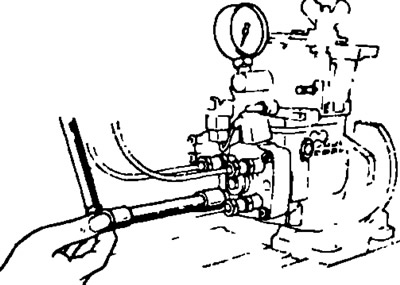
- P) Bleed the air from the high pressure fuel pipes.
- R) Let the injection pump run for 5 minutes at 2000 rpm.
Note: Check for fuel leaks and strange noises.
Note:
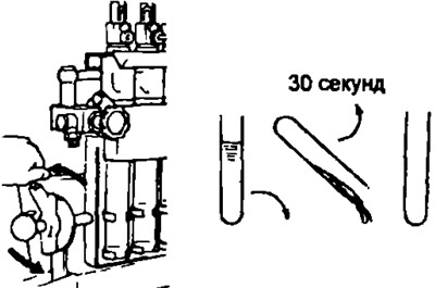
- Determine the volume of fuel in volumetric flasks (beakers).
- Before the next measurement, drain the fuel from the beaker for at least 30 seconds.
2. (2S-T) Perform a leak test on the boost pressure corrector.
- A) Actuate the boost pressure corrector, increasing the pressure to 1.22 bar for 10 s, repeat this operation 4 times.
- b) Apply a pressure of 1.36 bar to the boost suppression corrector.
- V) Measure the time it takes for the pressure to drop to 1.34 bar. Permissible pressure drop time: more than 10 s.
- G) Create a vacuum of 548 mmHg. on the fitting of the boost pressure corrector.
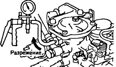
- d) Measure the time it takes for the vacuum to drop to 540 mmHg. Permissible vacuum fall time: more than 5 s.
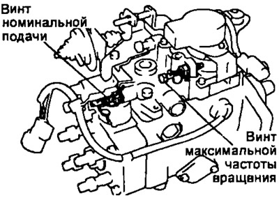
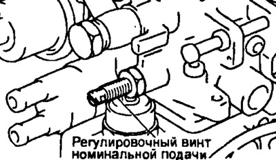
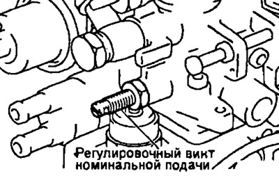
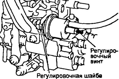
3. Preliminary adjustment of nominal fuel supply.
- A) Set the top of the injection pump control lever to the maximum feed position.
- b) (2S-T) Apply a pressure of 1.16 bar to the boost corrector.
- V) Measure the amount of fuel supply, (see table 1).
- G) If there is an O-ring seal, while holding the rated feed adjusting screw, release the sealing collar from the weld by turning the locknut counterclockwise 90°or more.
Table 1
| Engine | High-pressure fuel pump drive shaft speed, rpm | Number of cycles | Fuel supply, cm3 |
| 2C (M/T) | 1500 | 200 | 8,99-9,33 |
| 2C (A/T) | 1500 | 200 | 8,29-8,63 |
| 2S-T | 1500 | 200 | 11,43-11,77 |
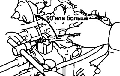
Use a screwdriver to remove the sealing collar.
- d) If there is a wire seal. cut the wire.
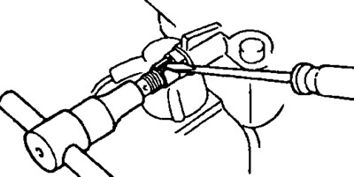
- e) Adjust the fuel supply by turning the fuel supply adjustment screw.
Note: Turning the nominal flow adjusting screw 1/2 turn changes the fuel delivery by approximately 3 cm3.
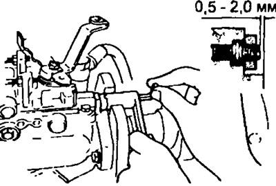
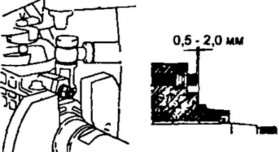
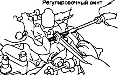
4. Preliminary adjustment of the position of the regulator shaft.
Using a special tool and an Allen key, adjust the protrusion of the governor shaft. Shaft protrusion: 0.5-2.0 mm.
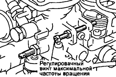
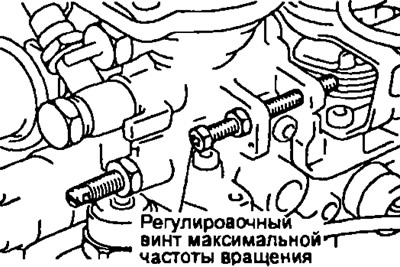
5. Preliminary adjustment of the maximum speed.
- A) Set the injection pump control lever to the maximum feed position.
- b) (2S-T) Apply a pressure of 1.16 bar to the boost corrector.
- V) Measure the amount of fuel supply (see table 2).
- G) Remove the seal from the maximum speed screw
- d) Adjust the feed rate with the maximum speed adjusting screw.
Table 2
| Engine | High-pressure fuel pump drive shaft speed, rpm | Number of cycles | Fuel supply, cm3 |
| 2C | 2700 | 200 | 2,0-3.2 |
| 2S-T | 1500 | 200 | 3.8-5.0 |
6. Adjust the fuel pressure inside the injection pump housing.
- A) Set the injection pump control lever to the maximum feed position.
- b) (2S-T) Apply a pressure of 1.16 bar to the boost corrector.
- V) Measure the fuel pressure inside the injection pump housing at the speeds indicated in table 3.
- G) If the pressure is less than the specified values, then adjust it with a metal rod with light blows on the stop of the pressure reducing valve spring, simultaneously observing the readings of the pressure gauge measuring the pressure inside the injection pump housing.
Table 3
| Engine | Frequency of rotation of the injection pump drive shaft. rpm | Internal pressure, kg/cm2 |
| 2C | 600 | 2,7-3,3 |
| 2C | 2100 | 6,47-7,07 |
| 2S-T | 600 | 3,3-3,9 |
| 2S-T | 2500 | 7,8-8,4 |
If the pressure exceeds the specified values or if the pressure reducing valve is ignited, then it must be replaced.
7. Check fuel volume.
- A) Set the injection pump control lever to the maximum feed position.
- b) (2S-T) Apply a pressure of 1.16 bar to the boost corrector.
- V) Measure the volume of fuel supplied through the fuel return hose from the injection pump housing at the speeds indicated in table 4.
Table 4
| Engine | Frequency of rotation of the injection pump drive shaft. rpm | The volume of the removed fuel, cm3 |
| 2C | 2100 | 167-364 |
| 2S-T | 2250 | 367-800 |
Note: Always install the fuel return pipe bolt that was installed on the injection pump.
8. For the following adjustments, turn off the engine warm-up control.
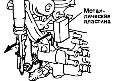
- A) Turn the heat control lever 20°counterclockwise.
- b) Place a 8.5-10 mm metal plate between the lever and the heat control actuator.
Note: Keep the overspeed warm-up system disabled until all measurements and adjustments have been made.
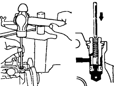
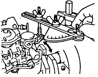
9. Measure and adjust the injection advance plunger stroke.
- A) Set the plunger stroke scale to zero.
- b) (2S-T) Apply a pressure of 1.16 bar to the boost corrector.
- V) Measure the injection advance plunger stroke at the given speeds.
Table 5
| Engine | High-pressure fuel pump drive shaft speed, rpm | Plunger stroke, mm |
| 2C manual transmission | 600 | 0,88-1,88 |
| 1500 | 5,02-6,02 | |
| 2100 | 7,78-8,78 | |
| 2S automatic transmission | 600 | 0,68-1.68 |
| 1500 | 4,92-5,92 | |
| 2100 | 7,75-8,75 | |
| 2S-T | 600 | 0,90-1,90 |
| 1300 | 3,69-4,69 | |
| 1800 | 5,69-6,69 | |
| 2350 | 6,32-6,80 |
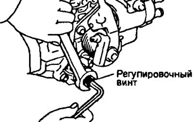
- G) Use a 5mm Allen key to adjust the advance plunger stroke.
Note: Plunger travel decreases when the screw is turned clockwise and increases when the screw is turned counterclockwise.
- d) (2S-T) Check the characteristic of the injection advance control spring.
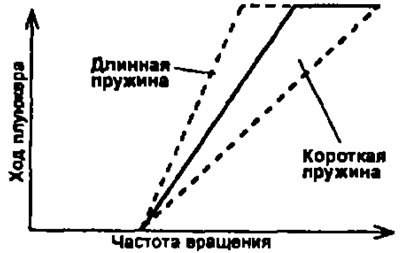
- e) (2S-T) If the characteristic differs from the specified one, select and replace the internal spring.
Spring free length 31.9 mm; 32.0 mm; 32.2mm; 32.3 mm; 32.5 mm.
Note; the stroke of the automatic advance piston increases with the lengthening of the spring.
10. Adjustment of cyclic feed at full load.
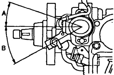
- A) Angle of rotation of the regulator lever: (A - maximum idle) - plus 13-23°, (B - minimum idle) minus 24-34°.
- b) (2S-T) Apply a pressure of 1.16 bar to the boost corrector.
- V) Measure cyclic flow at full load (see above table 1).
- G) Adjust the fuel supply at full load with the rated supply adjusting screw.
Note: The amount of feed changes by approximately 3 cm3 for every half turn of the screw.
11. Adjustment at maximum speed.
- A) (2S-T) Apply a pressure of 1.16 bar to the boost corrector;
- b) Measure the volume of injected fuel at maximum speeds.
Table 6
| Engine | High-pressure fuel pump drive shaft speed, rpm | Fuel supply, cm3 |
| 2C | 2600 | 4,5-6,3 |
| 2700 | 2,0-3,2 | |
| 2950 | 0.7 or less | |
| 2S-T | 2500 | 3,8-5,0 |
| 2600 | 5,86-8,26 | |
| 2900 | 0.7 or less |
Number of cycles: 200
Angle of rotation of the injection pump control lever: plus 13 - 23°
- V) Adjust the amount of injected fuel with the maximum speed adjusting screw.
12. Check up volume of injected fuel.
- A) Measure the volume of injected fuel at the speed and pressure on the boost corrector indicated in table 7.
Number of cycles: 200.
Angle of rotation of the injection pump control lever: plus 13-23°
For 2C-T, the pressure on the boost corrector:
- at 100 rpm: 0 bar
- for others: 1.16 bar
Table 7
| Engine | High-pressure fuel pump drive shaft speed, rpm | Fuel supply, cm3 | Permissible non-uniformity, cm3 |
| 2C manual transmission | 100 | 8,6 - 13,4 | 1,2 |
| 500 | 7,87-8,77 | 0,5 | |
| 1500 | 8,99-9,33 | 0,4 | |
| 2350 | 7,61-8,51 | 0,5 | |
| 2500 | 6,93-8,19 | 0,5 | |
| 2S automatic transmission | 100 | 8,6-13,4 | 1,2 |
| 500 | 6,81-7,71 | 0,5 | |
| 1500 | 8,29-8,63 | 0,4 | |
| 2350 | 7,19-8,09 | 0.5 | |
| 2500 | 6,39-7,65 | 0,5 | |
| 2S-T | 1500 | 11,43-11,77 | 0,4 |
| 100 | 9.6-14,4 | 1,2 | |
| 2100 | 9,66-10,56 | 0,5 | |
| 2250 | 8,8-10,06 | 0,5 |
- b) If the value of the starting feed (at 100 rpm) does not correspond to the table value, then replace the plug of the regulator sleeve: Press the plug out of the regulator sleeve.
- V) Remove the following parts: 1 - retaining ring, 2 - thrust ring, 3 - thrust bearing, 4 - plug.
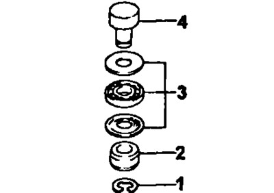
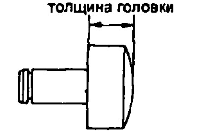
- G) Measure the thickness of the bushing plug head, select a new bushing plug. Note: lengthening the plug by 0.1 mm increases the starting feed by 0.6 cm3/200 cycles. If the supply unevenness exceeds the specified value, then replace the discharge valve.
Corks are available with different head thicknesses (in steps of 0.1 mm):
- 2C from 2.2 to 3.4 mm
- 2С-Т from 3.0 to 4.2 mm
- d) Assemble the regulator bushing in the reverse order of disassembly, press the plug into the bushing.
13. (2S-T) Minimum feed rate adjustment at full load.
- A) Set the injection pump control lever to the maximum position.
- b) Relieve pressure at the boost adjuster.
- V) Measure the fuel supply at the injection pump drive shaft speed of 700 rpm and the number of cycles - 200. Fuel supply: 6.8-7.4 cm3.
- b) The change in feed is carried out by turning the stop of the stroke limiter of the corrector rod.
14. (2S-T) Boost pressure adjustment.
A. Adjustment of the characteristics of the boost corrector.
- A) Set the injection pump control lever to the maximum feed position.
- b) Apply a pressure of 0.34 bar to the boost corrector.
- V) Measure the fuel supply at the injection pump drive shaft speed of 700 rpm and the number of cycles - 200. Fuel supply: 7.4-8.2 cm3.
- G) Remove the manifold drain screw and gasket.
- d) Adjust the fuel supply by turning the corrector rod guide bush (turning clockwise increases the feed.
- e) Install a new gasket and corrector drain screw.
B. Checking the slope of the boost correction characteristic
- A) Set the injection pump control lever to the maximum position.
- b) Apply a pressure of 0.86 bar to the boost corrector.
- V) Measure the fuel supply at a frequency of rotation of the injection pump drive shaft of 700 rpm and the number of cycles - 200. Fuel supply 10.26-11.05 cm3.
B. Measure the hysteresis. Compare the cyclic fuel supply when the pressure on the corrector increases from 0 to 1.36 bar and when the pressure decreases from 1.36 bar to 0. See table 6.
Table 8
| High-pressure fuel pump drive shaft speed, rpm | Pressure on the boost corrector, bar | Fuel supply, cm3 | Hysteresis, cm3 |
| 1500 | 1,36 | 12.0 or less | 0,5 |
| 1500 | 1,22 | 11,30-11 90 | 0,5 |
| 700 | 0,88 | 10,26-11,06 | 0,5 |
| 700 | 0,34 | 7,40-8,20 | 0,5 |
| 700 | 0 | 6,80-7,40 | 0,3 |
Note: when taking the characteristic when the pressure drops, turn the injection pump control lever from the idle position towards the maximum mode. Measurements were taken three times for each case.
The number of cycles is 200.
Angle of rotation of the injection pump control lever - plus 13-23°
If there is an increased hysteresis, check the quality of the assembly of the corrector and the presence of a sufficient amount of lubricant.
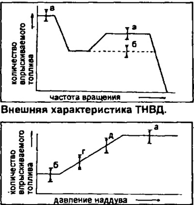
Characteristics of the boost corrector: a - adjust the cyclic flow, b - adjust the minimum flow at full load, c - adjust the starting flow at cold start, d - adjust the characteristic of the corrector for boost pressure, e - adjust the slope of the characteristic of the corrector for boost pressure.
15. Adjust the position of the governor shaft according to the load.
- A) Adjustment is carried out by turning the shaft of the regulator sleeve. Adjust the start and end points of the speed control clutch travel.
- b) Set the injection pump control lever to the maximum feed position.
- V) (2S-T) Apply a pressure of 0.41 bar to the boost corrector.
- G) Measure the fuel supply.
Number of cycles 200
Rotation frequency: 2C 1500 rpm; 2S-T 1800 rpm.
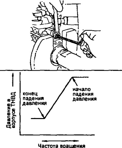
- d) Slowly move the lever towards the minimum idle stop and secure the lever at the point where pressure in the pump housing begins to drop.
- ё) Measure the flow at the point where the pressure drop begins. Calculate the difference in feeds and compare with the data in the table.
Table 9
| Engine | Rotation frequency, rpm | Number of cycles | Feed difference, cm3 |
| 2C | 1500 | 200 | 1,0±0,3 |
| 2S-T | 1800 | 200 | 1,0±0,3 |
- and) Adjust the feed difference by turning the governor shaft.
Note - half a turn of the governor shaft changes the feed by 3 cm.
- h) Slowly move the lever towards the minimum idle stop and secure the lever at the point where pressure in the pump housing stops dropping.
Compare the amount of fuel supply given in table 10.
- And) Check the difference in the stroke of the plunger of the injection advance machine according to the load when the injection pump control lever is moved from the position of the maximum speed to the position of idling. See table 11.
- To) (2S-T) If the difference in stroke of the injection advance automatic plunger does not correspond to the values indicated in the table, then select a new bushing with a hole of the required diameter.
Note: Increasing the bore diameter increases the travel difference.
Table 10
| Engine | High-pressure fuel pump drive shaft speed, rpm | Fuel supply, cm3 |
| 2C manual transmission (with exhaust gas recirculation) | 1500 | A-2.7±0.3 |
| 2C manual transmission (without exhaust gas recirculation) | 1500 | A-2.5±0.3 |
| 2S automatic transmission | 1500 | A-2.3±0.3 |
| 2S-T | 1800 | A-2.3±0.3 |
Note: where A is the value measured in subparagraph, d) paragraph 15.
Table 11
| Engine | High-pressure fuel pump drive shaft speed, rpm | Plunger stroke difference, mm |
| 2C manual transmission (with exhaust gas recirculation) | 1500 | 2,16-2.76 |
| 2C manual transmission (without exhaust gas recirculation) | 1500 | 1,75-2,35 |
| 2S automatic transmission | 1500 | 1,34-1,94 |
| 2S-T | "1800 | 1,34-1,94 |
- l) Measure the protrusion of the governor shaft. Shaft protrusion 0.5-2.0 mm.
16. Idling feed adjustment.
- A) (2S-T) Loosen the damper control lever bolt.
- b) Measure the feed at different speeds of the injection pump drive shaft. (See table 12).
Table 12
| Engine | Frequency of rotation of the injection pump drive shaft. rpm | Fuel supply, cm3 | Note |
| 2C | 400 | q = 1,65.-2,55 | adjust |
| 475 | q - (1,2...2,2) | - | |
| 375 | q + 0.5 or more | - | |
| 2S-T | 400 | q = 2,05...2,95 | adjust |
| 600 | q - (1,2...2,2) | - | |
| 375 | q + 0.5 or more | - |
The angle of rotation of the injection pump control lever: minus 24-34°.
Number of cycles: 200.
Allowable unevenness: 0.34 cm3.
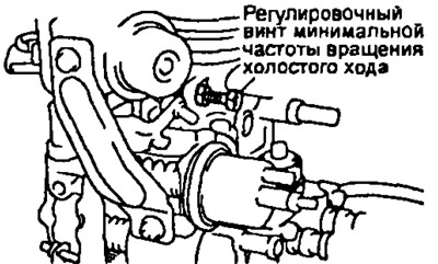
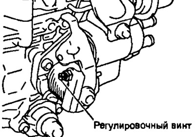
- V) Adjust the injection fuel supply at the minimum idle speed mode with the adjusting screw of the minimum idle speed.
17. (2S-T (modifications)) Adjust damper.
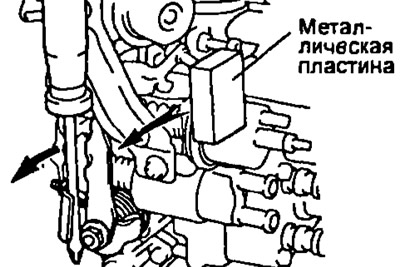
- A) Install a metal plate between the #1 adjusting lever and the idle speed adjusting screw.
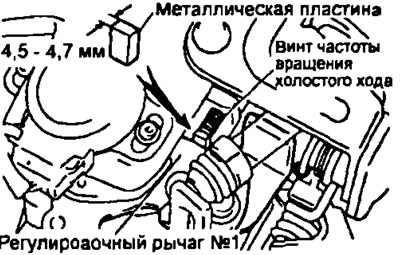
- b) Move the damper control lever until it touches the damper rod.
- V) Fix the lever with a bolt. Tightening torque: 8 Nm.
- G) Check that the damper rod does not press on the damper control lever.
18. Adjust the heating control system.
- A) Remove the fuel return pipe mounting bolt and measure the fuel temperature inside the injection pump housing. Fuel temperature: 15-35°C.
- b) Install the injection pump drive shaft so that the segment key is in a vertical or horizontal position.
- V) Set the scale of the injection advance plunger stroke gauge to zero.
- G) Check the initial angular position of the adjusting lever for controlling the heating of the high-pressure fuel pump, which we will consider as zero.
- d) Remove the metal plate that was installed between the adjusting lever and the heat control actuator.
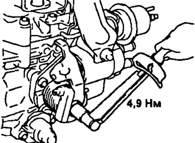
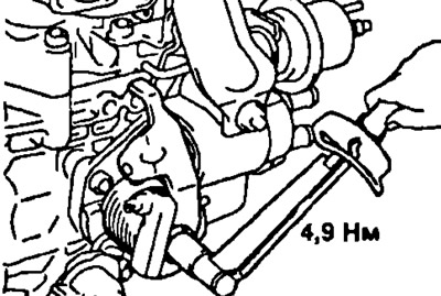
- e) Turn the automatic control lever of the warm-up control clockwise with a force of approximately 4.9 Nm and hold it in this position with a torque wrench at the specified gain for 10 seconds, then remove the force.
- and) Measure the injection advance plunger stroke at a temperature of 25°C and an injection pump drive shaft speed of 400 rpm.
Plunger stroke:
- 2C with manual transmission 0.74-1.14 mm
- 2SSAKPP 0.55 - 0.95 mm
- 2S-T 0.91 - 1.31 mm
If it is out of specification, adjust it with the adjusting screw.
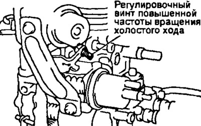
19. Adjust the high idle speed.
2C
- A) Measure the clearance between the control lever and the idle speed adjusting screw.
Gap at fuel temperature: 25°C 1.4 mm; 50°C 0 mm.
- b) Adjust the clearance by turning the high idle adjusting screw.
2С-T
- A) For the following adjustments, turn off the engine warm-up control.
- Turn the heat control lever 20°counterclockwise.
- Place a 8.5-10 mm metal plate between the lever and the heat control actuator.
- b) Set the control lever to the idle position.
- V) Measure the injected fuel supply at the injection pump drive shaft speed of 400 rpm and the number of cycles - 200. Fuel supply q \u003d 2.05-2.95 cm3
- G) Remove the metal plate between the lever and the heat control actuator.
- d) Turn the automatic control lever of the warm-up control clockwise with a force of approximately 4.9 Nm and hold it in this position with a torque wrench at the specified force for 10 seconds, then remove the force.
- V) Measure the fuel supply at an injection pump drive shaft speed of 400 rpm and a number of cycles of 200. Fuel supply q plus 1.5-1.9 cm3.
- and) Adjust the fuel supply by turning the high idle adjusting screw.
20. (2S-T) Adjust the increase in idle speed when the air conditioner is turned on.
- A) For the following adjustments, turn off the engine warm-up control.
- Turn the heat control lever 20°counterclockwise.
- Place a 8.5-10 mm metal plate between the lever and the heat control actuator.
- b) Create a vacuum of 300 mmHg. in the drive system to increase the idle speed when the air conditioner is turned on.
- V) Set the control lever to the idle position.
- G) Measure the injected fuel supply at the injection pump drive shaft speed of 450 rpm and the number of cycles - 200. Fuel supply 1.8-2.6 cm3
- d) Adjust the fuel supply by turning the adjusting screw of the idle speed increase drive system when the air conditioner is turned on.
If you cannot adjust with the screw, adjust with shims.
- e) Remove the metal plate between the lever and the heat control actuator.
21. Check after adjustment.
- A) Check that the flow stops when the fuel cut off solenoid valve is disconnected. High-pressure fuel pump shaft speed: 100 rpm.
- b) (2S-T) For the following adjustments, turn off the engine warm-up control.
- Turn the heat control lever 20* counterclockwise.
- Place a 8.5 - 10 mm metal plate between the lever and the heat control actuator.
- V) Check the movement of the control lever. Adjusting angle of the control lever position 42-52°.
- G) Remove the metal plate between the lever and the heat control actuator.
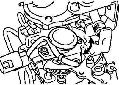
22. Adjust the control lever position sensor.
- A) Set the control lever to the position corresponding to the amount of fuel injected, shown in table 13. Number of cycles: 200.
Table 13
| Engine | High-pressure fuel pump drive shaft speed, rpm | Fuel supply, cm3 |
| 2C | 700 | 5,6 |
| 2S-T | 1000 | 5,12-5,28 |
- b) Loosen the two screws securing the control lever position sensor to the bracket.
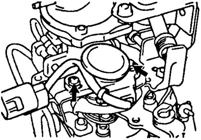
- V) Apply 5V between pins "VC" And "E2".
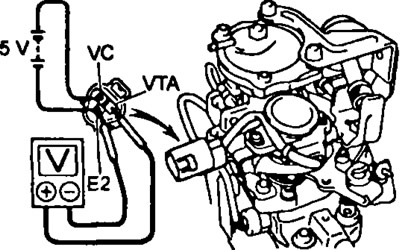
- G) Connect a voltmeter to the terminals "VTA" And "E2" control lever position sensor.
- d) Slowly turn the control lever position sensor so that the output voltage becomes: 2C: 2.14±0.025V; 2C-T: 2.97±0.025 V.
23. Remove the injection pump from the stand.
24. Install seals. Seal the adjusting screws for maximum speed and nominal feed (full load) new wire seals.