A) Type and adjustment of bench nozzles:
Bench nozzle: DN12SD12 (NIPPONDENSO)
- Spray needle opening pressure: 145 - 155 bar.
b) Bench tachometer error:±40 rpm.
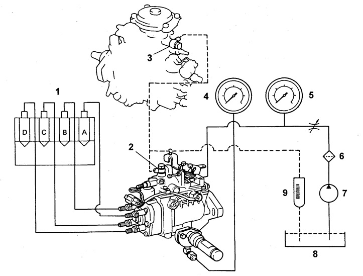
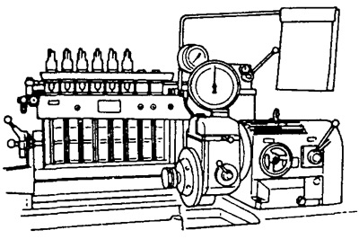
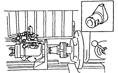
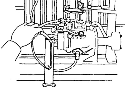
Stand scheme.
1 - nozzles,
2 and 3 - fuel return line,
4 and 5 - fuel pressure gauges,
6 - stand filter,
7 - stand pump,
8 - stand fuel tank,
9 - stand flowmeter.
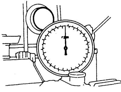
V) Set the bench dial to zero.
G) Install the pump on the stand.
Reminder. Place a mark on the coupler against the pump shaft key.
d) High pressure pipes:
- Outer diameter - 6.0 mm
- Inner diameter - 2.0 mm
- Length - 840 mm
- Minimum bending radius - 25 mm
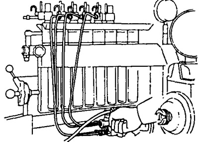
e) Connect bench tubes of a supply and removal of fuel. Install adapters if necessary.
Caution: Secure the fuel outlet pipe only with the pump bolt (bolt with jet, marking OUT).
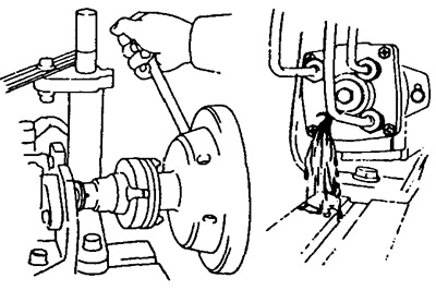
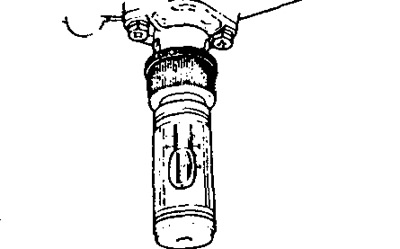
and) Remove the right cover of the advance machine.
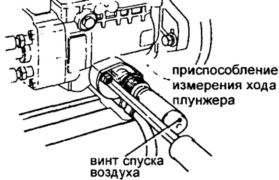
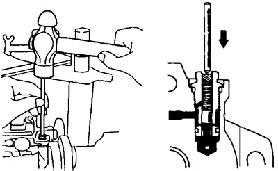
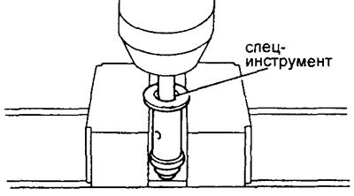
h) Install NIPPON-DENSO Plunger Stroke Tool P/N 95095-10220 and P/N 95095-10231.
And) Apply +12V to the fuel cut-off valve (from stand system or battery).
To) The fuel supply pressure to the pump must be 0.2 bar. The temperature of the fuel during testing should be 40 - 45°C.
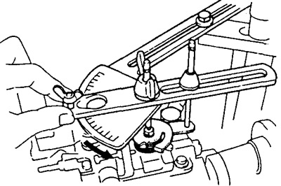
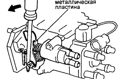
l) Install the protractor on the injection pump lever.
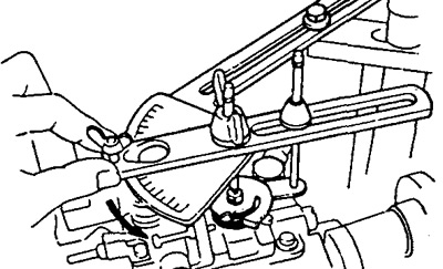
m) Lock the pump control lever in the maximum speed position.
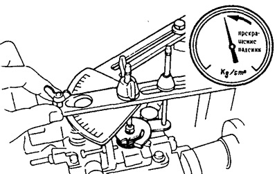
n) Check the correct orientation of the cam (correct assembly):
Remove the nozzle pressure valve "WITH".
Align the key position mark on the coupling with the fitting "WITH". Turn on the booster pump of the stand. If fuel does not flow out of the nozzle "WITH" disassemble the pump and change the position of the cam by 180°.
O) Set the pump to 2000 rpm for 5 minutes. Check for fuel leaks and unusual noise.
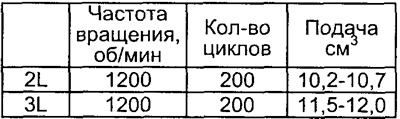
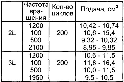
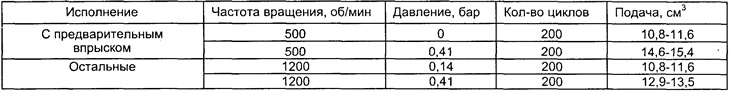
2. Pre-setting of cyclic feed at full load.
A) Set the injection pump control lever to the maximum position.
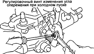
b) Measure the amount of fuel supplied. (See table. 1)
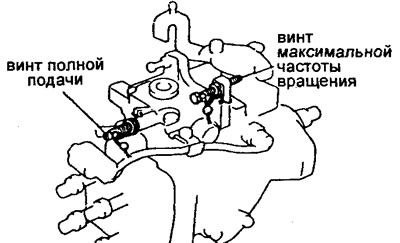
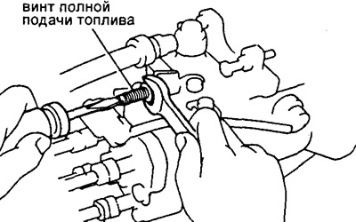
V) Remove the O-ring from the maximum feed screw (the seal is welded by turning welding) or cut the wire of a conventional seal.
d) Adjust the cyclic feed by turning the full feed screw.
Note: The cycle feed will increase by approximately 300-1200 cycles for each ½ turn of the screw.
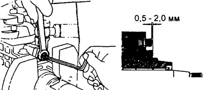
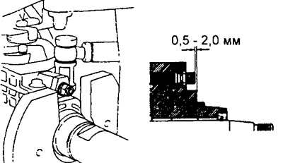
3. (With height compensator).
Load injection advance controller pre-setting. Install the governor shaft outlet.
- Exit distance — 0.5-2.0 mm
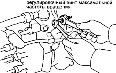
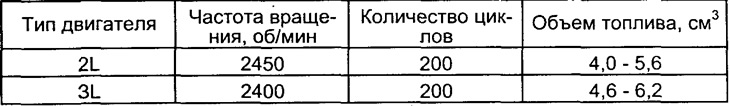
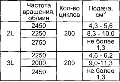
4. Presetting the maximum speed.
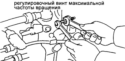
A) Set the control lever to the maximum speed stop.
b) Remove stop screw seal.
V) Adjust the cyclic feed by turning the screw of the maximum speed stop, (see table. 2).
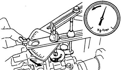
5. Pressure adjustment of the booster pump.
A) Measure the pressure in the pump housing.
Speed - Pressure
- 500 rpm - 3.2- 3.8 bar
- 2100 rpm - 6.6-7.2 bar
b) If the pressure is low, then adjust it with light strokes on the piston of the pressure reducing valve, controlling the pressure gauge readings.
Caution: If the pressure is too high or the pressure reducing valve spring preload is at its maximum, replace the pressure reducing valve.
6. Checking the fuel consumption for return to the tank. Measure return fuel flow at 2200 rpm.
- Fuel consumption - 70-380 cm3/min
Caution: Always install the fuel return pipe mounting bolt (with jet and OUT mark), belonging to the pump.
Table 1
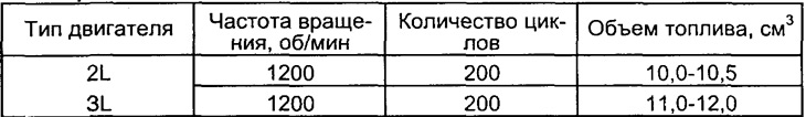
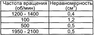
table 2
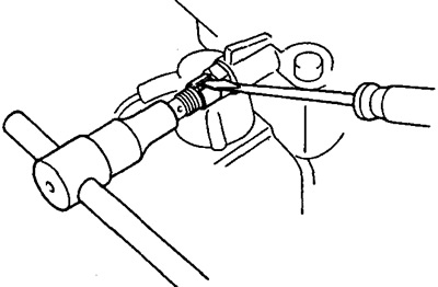
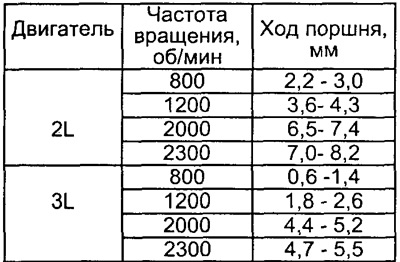
7. Adjustment of the automatic injection advance.
A) Set the measuring device to zero.
b) Measure the stroke of the automatic advance piston at the following speeds.
 |  |
Attention: The hysteresis should not be more than 0.3 mm.
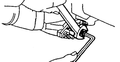
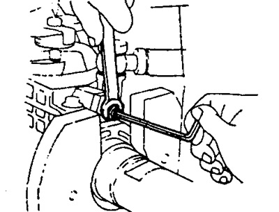
V) Use a 5mm Allen key to adjust the stroke of the injection advance plunger.
Note: Plunger travel decreases when the screw is turned clockwise and increases when the screw is turned counterclockwise.
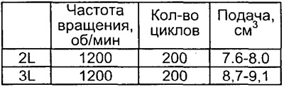
8. Adjustment of cyclic feed at full load.
A) Adjuster Lever Angle: All Models
- plus (A) 23...33 degrees
- minus (IN) 13...21 degrees
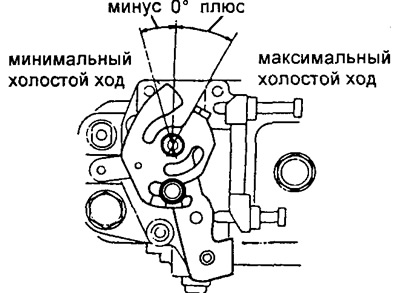
V) Adjust by turning the full feed screw.
Note: The feed will increase by about 3cm3/200 cycles for every ½ turn of the screw.
 |  |
9. Feed adjustment at maximum idle speed.
A) Adjust by turning the maximum speed screw.
10. Adjustment of giving on the external characteristic.
Permissible feed unevenness
If the starting feed value (at 100 rpm) does not correspond to the table value, then replace the plug of the regulator bushing:
Press the plug out of the regulator bushing.
Remove:
- (1) retaining ring;
- (2) spacer;
- (3) thrust bearing;
- (4) cork.

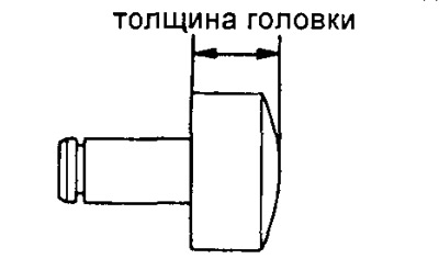
Measure the thickness of the bushing plug head, select a new bushing plug.
Note:
- Lengthening the cork by 0.1 mm increases the starting feed by 0.6 cm3/200 cycles. If the supply unevenness exceeds the specified value, then replace the discharge valve.
- Stoppers are produced with a head thickness from 3.0 to 4.2 mm in 0.1 mm increments.
Assemble the regulator bushing in the reverse order of disassembly, press the plug into the bushing.
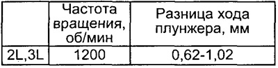
11. Adjustment of automatic injection advance (by load).
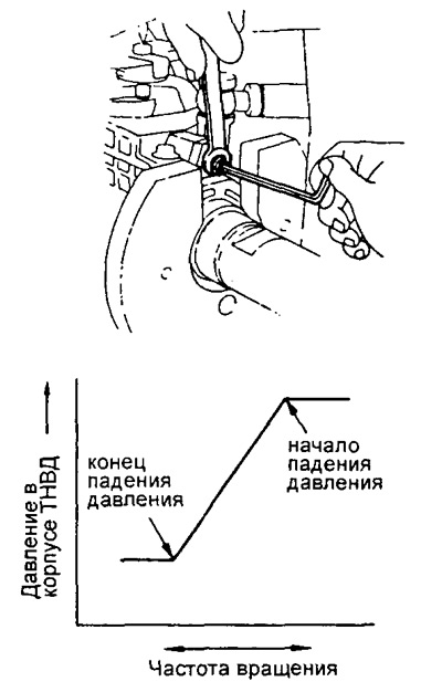
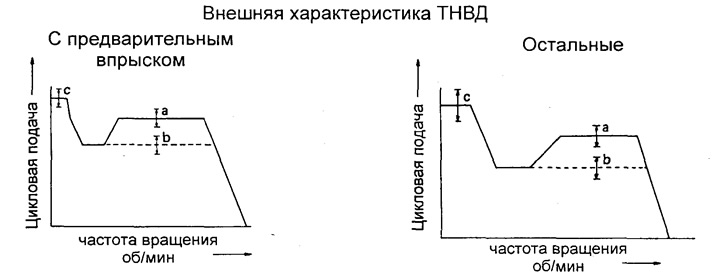
Table 3
A) Adjustment is carried out by turning the shaft of the regulator sleeve. The beginning of the operation of the machine at a speed of 1200 rpm.
b) Move the control lever to the maximum speed position and measure the amount of fuel supply.
V) Slowly move the lever towards the minimum idle stop and secure the lever at the point where the pressure in the pump housing begins to drop.
G) Measure the flow at the point where the pressure drop begins. Calculate the difference in feeds and compare with the data in the table.
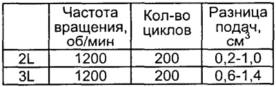
d) Adjust feed difference.
Note: Half a turn of the governor shaft changes the feed by 3 cm3/200 cycles.
e) Move the control lever to the point where the pressure drop in the pump casing stops, secure the lever.
Compare the amount of fuel supply with the data in the table.
and) Check the change in stroke of the injection advancer plunger at the start and end points of the pressure change in the pump.
 |  |
h) Measure the protrusion of the governor shaft.
- Protrusion - 0.5-2.0 mm
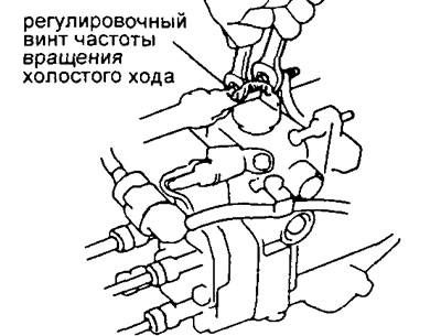
12. Adjusting the idle speed and checking the minimum speed controller (see table. 4)
Adjust the feed by turning the minimum idle screw.
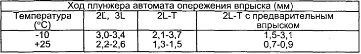
13. Adjustment of advance angle change at cold start.
A) Measure the temperature of the fuel at the pump.
- Fuel temperature - 15 - 35°С
b) Install the pump shaft key vertically.
V) Set the injection advance plunger stroke meter to zero.
Table 4. 2L and 3L engines
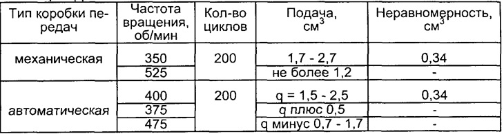
G) Set the pump control lever to the stop and take the angle of rotation of the lever as zero.
d) Delete (if installed) plate between the heating control lever and the thermostat.
e) Turn the heating control lever clockwise to a torque of 5 Nm and hold the torque for 10 seconds.
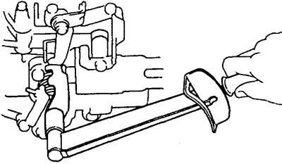
and) Measure advance plunger stroke (see table. 5).
h) Adjust the plunger stroke by turning the adjusting screw.
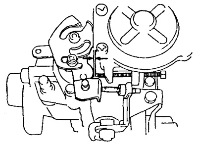
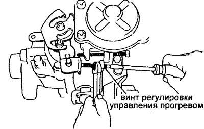
14. Adjusting the heating control system
A) Measure the clearance between the control lever and the minimum idle screw.
Table 5
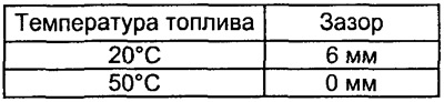 |  |
b) Adjust the gap by turning the screw in the heat control lever.
15. Sealing elements.
Install the seals on the screws for maximum speed and full fuel supply.