
Rated axial clearance:
- EJ series - 0.150-0.250 mm
- KZ series - 0.100 - 0.300 mm
Maximum axial clearance:
- EJ series - 0.300 mm
- KZ series - 0.350 mm
If the end play is greater than the maximum, replace the connecting rod assembly. Replace crankshaft if necessary.
2. Remove the cover of the lower head of the connecting rod and check the radial clearance of the connecting rod bearing.
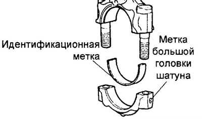
A) Check alignment of marks on connecting rod and connecting rod cap to ensure correct reassembly later on.
If there are no marks, apply them to the caps and connecting rods.
b) Loosen two screws (KZ series) or nuts (EJ-series) fastening the cap of the lower head of the connecting rod.
V) Remove the connecting rod cover.
Note: The bottom half of the bushing must remain in the connecting rod cap.
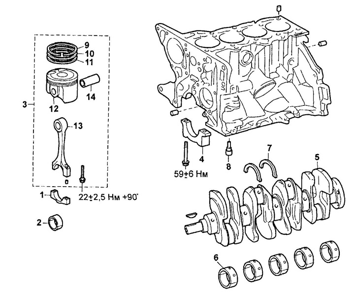
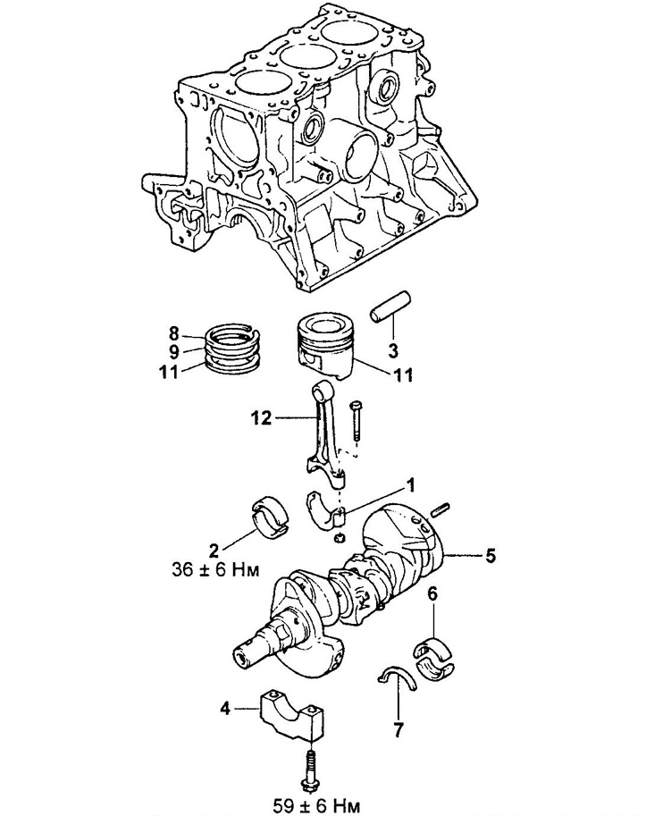
Dismantling and assembly of the block of cylinders (KZ series).
1 - connecting rod cover,
2 - connecting rod bearing shells,
3 - piston with connecting rod assembly,
4 - main bearing cap,
5 - crankshaft,
6 - main bearing shell,
7 - persistent half ring,
8 - oil nozzle,
9 - compression ring No. 1,
10 - compression ring No. 2,
11 - oil scraper ring,
12 - piston,
13 - connecting rod,
14 - piston pin.
G) Clean the crankpin and bearings.
d) Check the connecting rod journal and bearing surfaces for pitting and scratches.
If there are scratches or scratches, replace the bearings. Replace crankshaft if necessary.
Note: Do not confuse the upper and lower bearing shells.
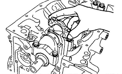
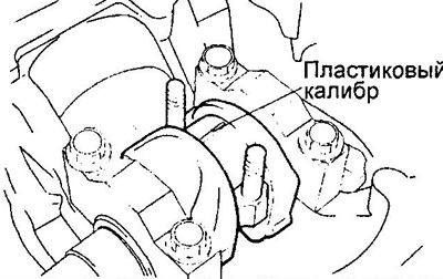
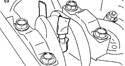
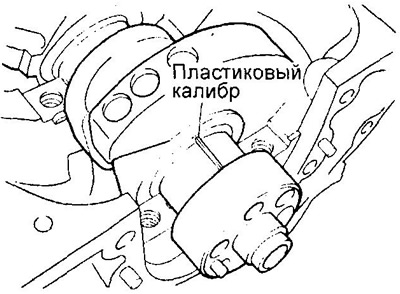
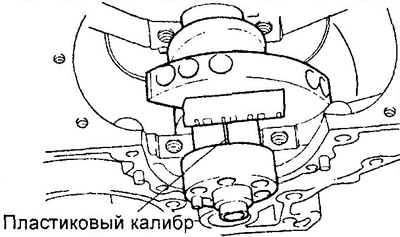
e) Install a plastic gauge to measure the clearances in the plain bearings across the crankpin.
and) Install the connecting rod lower cover by aligning the match marks. Tighten the bolts (KZ series) or nuts (EJ-series) mounts (see subsection "Assembly" section "Cylinder block").
Note:
- Do not rotate the crankshaft.
- Apply some oil to the threads and under the bolt heads before installing them.
Torque:
EJ Series - 36±6 Nm
KZ series:
- 1st stage — 22±2.5 Nm
- 2nd stage - tighten by 90°
h) Remove the bottom cover of the connecting rod by unscrewing the bolts / unscrewing the nuts.
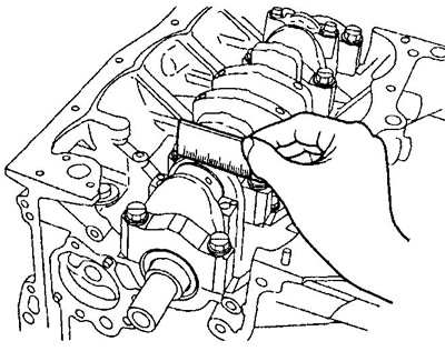
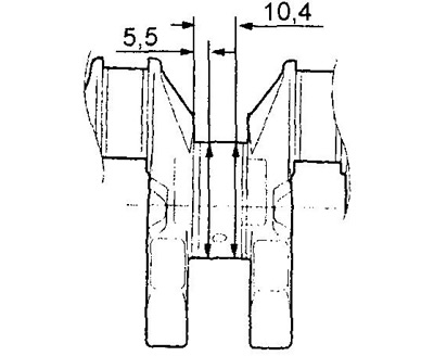
And) Measure the maximum width of the flattened gauge wire to determine the radial clearance of the connecting rod bearing.
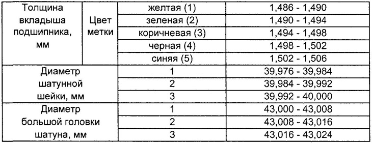
Connecting rod bearing clearance:
EJ Series:
- nominal - 0.020 - 0.044 mm
- maximum - 0.070 mm
KZ series:
- nominal - 0.016 - 0.040 mm
- maximum - 0.070 mm
(EJ-series) If the clearance is greater than the maximum, replace the connecting rod bearing shells.
(KZ series) If the clearance is greater than the maximum, check the diameter of the crankshaft journal, the inner diameter of the big end of the connecting rod, and the thickness of the bearings. Replace worn parts.
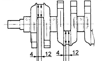
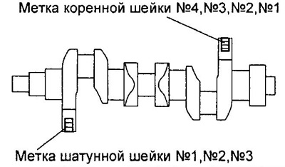
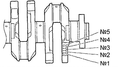
To) (KZ series) Measure the diameter of the connecting rod journals of the crankshaft in four mutually perpendicular directions, as shown in the figure.
- Nominal diameter - 39.992 - 40.000 mm
Series K3
l) (KZ series) Measure the inside diameter of the big end of the connecting rod.
- Nominal diameter - 43.000 - 43.008 mm
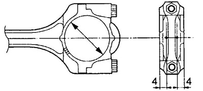
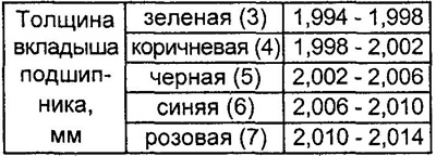
m) (KZ series) Measure the thickness of the connecting rod bearing.
- Nominal thickness - 1.488 - 1.492 mm
Note: If necessary, grind the crankshaft to repair size.
- Rem. (0,25) - 39.726 - 39.766 mm
n) (EJ-series) Replace the connecting rod bearing shells with new ones. Use bearings that have the same mark as those used, or select new bearings from the table "Selection of connecting rod bearing shells (EJ-series) ". Do not regrind the crankshaft.
Check identification marks.
 |  |
O) Remove the remnants of the calibration wire from the working surfaces of the neck and liner.
3. Remove the piston and connecting rod assembly.
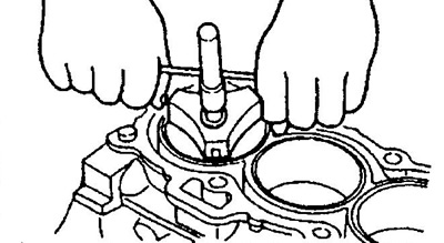
A) Use a reamer to remove carbon deposits from the top of the cylinder.
Dismantling and assembly of the block of cylinders (EJ-series).
1 - connecting rod cover,
2 - connecting rod bearing shells,
3 - piston pin,
4 - main bearing cap,
5 - crankshaft,
6 - main bearing shell,
7 - persistent half ring,
8 - compression ring No. 1,
9 - compression ring No. 2,
10 - oil scraper ring,
11 - piston,
12 - connecting rod.
Table. Selection of connecting rod bearing shells (EJ-series).
Note: Connecting rod bearing mark = big end mark - crankshaft journal mark.
b) Remove the piston assembly with connecting rod and upper bearing shell through the top of the cylinder block.
Note: (EJ-series) put rubber hoses on the threads of the bolts to avoid damage.
EJ series.
Note:
- Keep bearings, connecting rod and cap together.
- Arrange the pistons with connecting rods and liners in order to match the cylinders.
4. Remove connecting rod bearings.
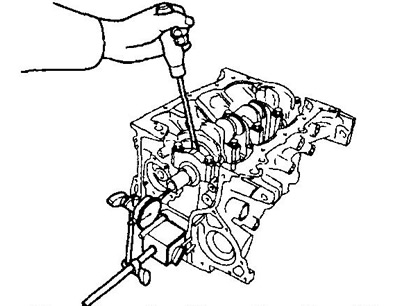
5. Use an indicator to measure the axial clearance of the crankshaft by moving the latter back and forth with a screwdriver.
- Rated axial clearance - 0.02 - 0.22 mm
- Maximum axial clearance - 0.30 mm
If the axial clearance is greater than the maximum, replace the thrust washers.
Thickness of thrust half rings:
- KZ series - 1.92 - 1.99 mm
- EJ-VE - 1.94-1.99mm
6. Remove the main bearing caps and check the radial oil clearances.
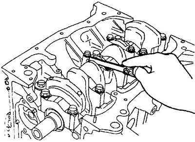
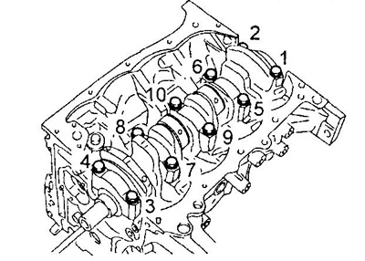
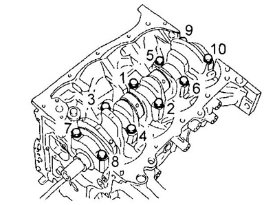
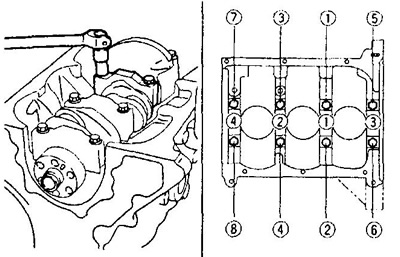
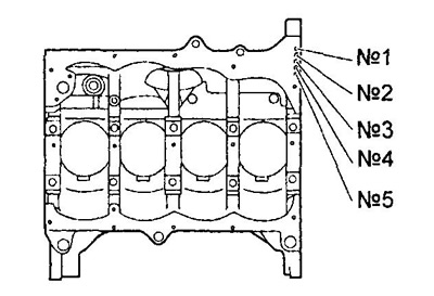
A) Loosen and remove the main bearing cap bolts evenly in several passes in the sequence shown in the illustration.
KZ series.
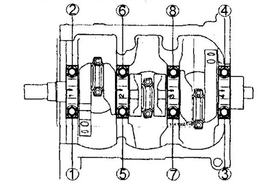
EJ-VE.
b) While shaking the unscrewed bolts in the holes of the main bearing caps, remove the caps together with the lower shells and lower thrust washers.
Note:
- Keep the main bearing caps together with the lower bearings.
- Position the main bearing caps and thrust washers in the order of assembly.
V) Raise the crankshaft.
Note: Leave the upper bearing shells and upper thrust washers in the cylinder block.
G) Clean each main journal and bearings.
d) Check the surface of each main journal and bearings for pitting and scratches. If the neck or insert is damaged, replace the inserts. Regrind or replace crankshaft if necessary.
e) Lay a cranked shaft in the block of cylinders.
and) Place a plastic bearing clearance gauge on each journal.
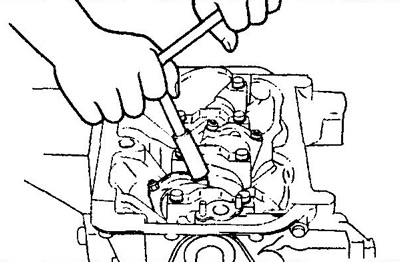
h) Establish covers of radical bearings and tighten bolts in the sequence shown in drawing.
- Tightening torque - 59±6 Nm
Note: Do not rotate the crankshaft.
KZ series.
EJ-VE.
And) Remove the main bearing caps.
To) Measure the maximum width of the flattened gauge wire to determine the radial clearance.
Main bearing clearance:
KZ series:
- nominal - 0.016 - 0.036 mm
- maximum - 0.070 mm
EJ Series:
- nominal - 0.004 - 0.028 mm
- maximum - 0.060 mm
(EJ-series) If the clearance is greater than the maximum, select new main bearing shells.
(KZ series)
If the clearance is much larger than the nominal, measure the diameter of the crankshaft main journals, the diameter of the main bearing beds in the cylinder block and the thickness of the liners (see below).
Replace worn parts.
If necessary, grind the crankshaft to the repair size and select new liners according to the formula: Measured diameter of the main journal + thickness of the new liner x 2 \u003d 0.016 - 0.036 mm
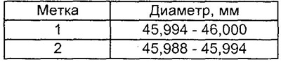
l) (KZ series) Measure the diameter of the crankshaft main journal at two points (A) And (IN).
- Nominal diameter - 45.988 - 46.000 mm
If the diameter is larger than the nominal, grind the crankshaft to the repair size.
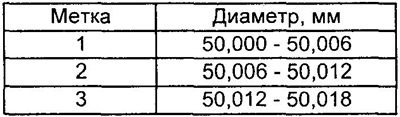
m) (KZ series) Measure the inside diameter of the main bearing bed in the cylinder block at two locations 3 mm from the edges of the support.
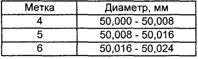
- Nominal diameter - 50.000 - 50.018 mm
Note: when replacing, it is necessary to use parts of the same size group as those being replaced.
Crankshaft journal mark (KZ series).
 |  |
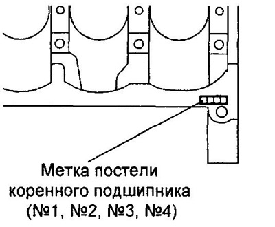
Label of a bed of the main bearing of the block of cylinders (KZ series).
 |  |
Main bearing bearing mark (KZ series).
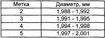 | 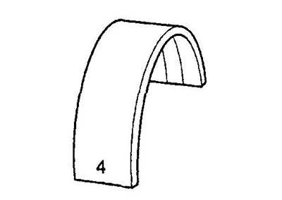 |
Table for determining the size groups of liners (KZ series).
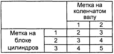
Example: label "3" on the cylinder block + mark "2" on crankshaft = sum "5" (required insert - No. 5).
n) (EJ-series) Pick up new liners of main bearings.
Label of a bed of the main bearing of the block of cylinders (EJ-series).
 | 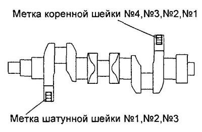 |
Crankshaft journal mark (EJ-series).
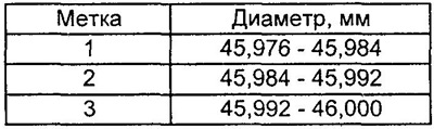 | 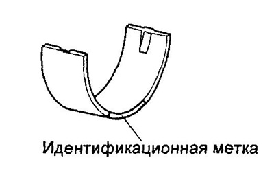 |
Table for determining the size group of the main journal bearing shell (EJ-series).
Example: main bearing mark = (mark of the bed of the main bearing of the cylinder block) - (crankshaft journal mark) + 2.
O) Remove the plastic gauges.
9. Remove the crankshaft.
A) Raise the crankshaft.
b) Remove the upper main bearing shells and upper thrust washers from the cylinder block.
Note: Install the main bearings and thrust washers in the order of installation.