
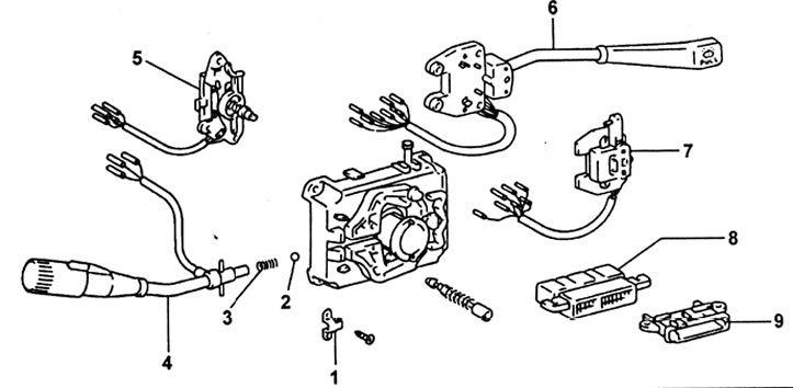
Combined switch. 1 - ball holder, 2 - ball, 3 - spring, 4 - light control switch, 5 - headlight switch, 6 - washer and wiper switch, 7 - direction indicator switch, 8 - connector, 9 - wire holder.
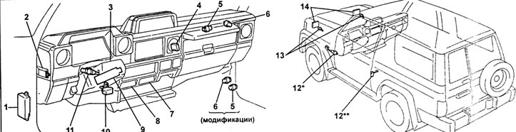
Lighting system. 1 - fuse box, 2 - headlamp leveling control switch, 3 - hazard warning switch and turn signal/headlight switches, 4 - daytime running lamp relay, 5 - rear fog lamp relay, 6 - hazard warning relay, 7 - rear fog light switch, 8 - front fog light switch, 9 - relay box, 10 - light warning relay, 11 - combination switch, 12 - front door limit switch (* - models with open door warning system, ** - models without open door warning system), 13 - headlight position adjustment drive, 14 - headlights.
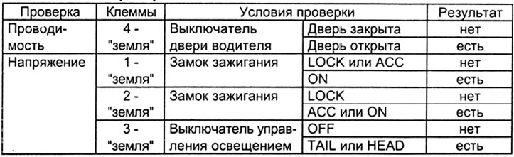
Table for checking the warning system about the presence of switched on lighting devices.
Headlight adjustment
Note: For headlights equipped with an electric positioning system, before adjusting, set the control switch to position "ABOUT", to reset the headlights.
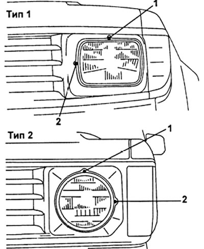
1 - adjustment in the vertical plane, 2 - adjustment in the horizontal plane.
Combination switch
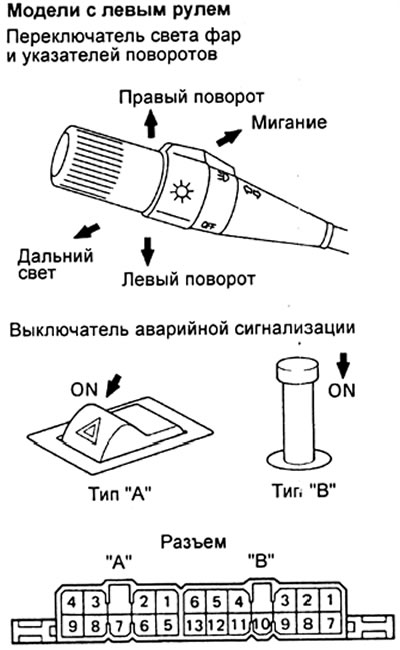
Note: The location of the switch on right hand drive models is symmetrical to its location on left hand drive models.
1. Checking the switch.
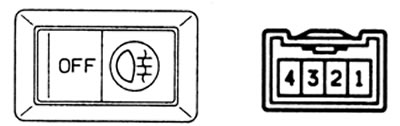
A) Check the continuity of the external light switch.
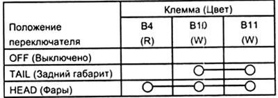
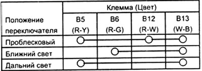
b) Check the conductivity of the headlight switch.
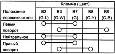
V) Check the continuity of the turn signal switch.
G) Check the continuity of the alarm switch.
d) Replace the combination switch if the conductivity differs from that given in the tables.
2. Checking the relay in the relay box.
A) Check the continuity of the headlight control relay.
b) Check the continuity of the rear position relay.
V) Check the continuity of the headlight switch relay.
G) Replace the relay if the conductivity is out of specification.
Fog lights
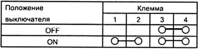
1. Checking the front fog light switch.
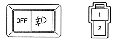
2. Checking the rear fog light switch.
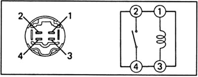
3. Checking the rear fog lamp relay.
Direction indicators and alarms
1. Check of switches of indexes of turn and the alarm system see in subsection "combination switch".
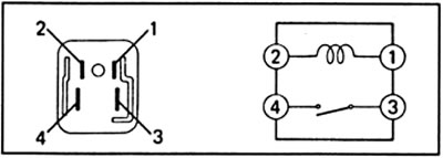
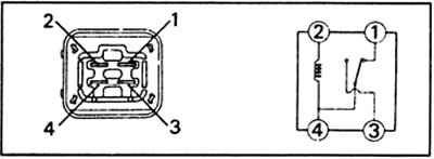
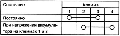
2. Checking the relay-interrupter of direction indicators.
A) Connect the battery to terminals 2 (+) and 3 (-) relay.
b) Connect both turn signal bulbs in parallel to terminals 1 and 3, check that the bulbs flash at a rate of 60-120 times per minute.
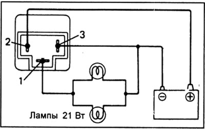
V) If one of the direction indicator bulbs is burned out, then the blinking frequency increases to 140 times per minute.
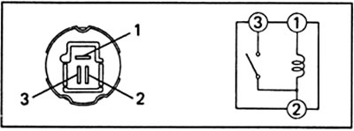
3. Check the alarm relay.
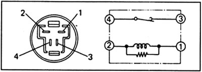
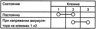
Warning system for the presence of switched-on lighting devices
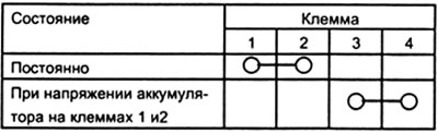
1. Check the operation of the system relay.
A) Connect the battery to terminals 3 (+) and 4 (-).
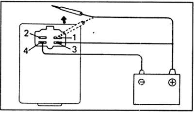
b) Switch "plus" battery from terminal 2 to terminal 1: the buzzer should not work.
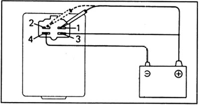
V) Disconnect "plus" battery from terminal 1 or 2: the buzzer should sound.
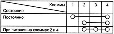
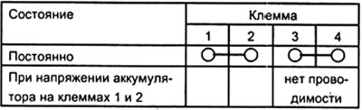
2. Check wiring.
A) Disconnect the relay connector.
b) Check the connector on the wire bundle side as shown in the table.
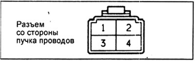
V) If the parameters of the electrical circuit do not correspond to those described in the table, then replace the relay. Repeat the test after replacing the relay and, if the circuit parameters again do not match the data in the table, check the circuits of other devices.
3. Checking the driver's door switch (models without door open warning system).
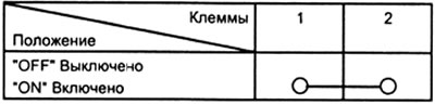
A) Check for continuity between the connector and the switch body when the switch is in the "ON" (button released).
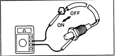
b) Check for continuity between the connector and the switch body when the switch is in the "OFF" (button pressed).
V) Replace the switch if it does not work as specified.
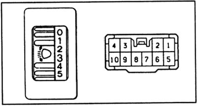
Electrically adjustable headlights
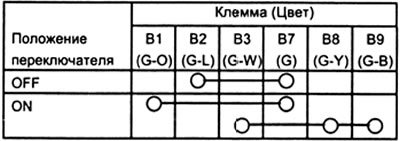
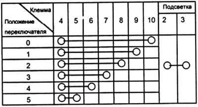
1. Check the continuity of the switch. Replace the switch if the conductivity differs from that given in the table.
2. Checking the drive.
A) Connect the battery to terminals 6 (+) and 5 (-).
b) Connect each terminal in turn to "earth" and check the operation of the drive in various modes.
| Terminal | Headlight Beam Position |
| 1 - "Earth" | "0" |
| 2 - "Earth" | "1" |
| 3 - "Earth" | "2" |
| 4 - "Earth" | "3" |
| 7 - "Earth" | "4" |
| 8 - "Earth" | "5" |
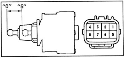
V) Replace the drive if it does not work as specified.