Fuel heater assembly with vacuum switch
1. Checking the fuel heater.
A) Create a vacuum of 0.35 bar at the switch.
b) Measure the resistance between the terminal "1" and switch housing
Resistance at 20°C:
- L series about 0.7 ohm
- KZ series 1.4 - 2.0 Ohm
If the resistance is not as specified, replace the fuel heater assembly with the vacuum switch.
Note: Connector configuration varies by model.
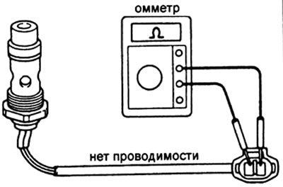
2. Checking the conductivity of the vacuum circuit breaker.
Use an ohmmeter to check for continuity between the terminal "1" and switch housing.
If there is continuity, replace the fuel heater assembly with the vacuum switch.
3. Checking the operation of the switch.
A) Create a vacuum of 0.35 bar at the switch.
b) Use an ohmmeter to check the continuity between the terminal "1" and switch housing. If there is no continuity, replace the fuel heater assembly with the vacuum switch.
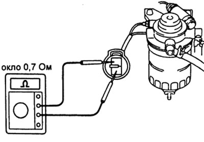
Fuel heater (3L engine)
Measure the resistance between the heater terminals.
Resistance - Approximately 0.7 ohm at 20°C
If the resistance is not as specified, replace the fuel heater assembly with the vacuum switch.
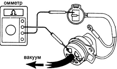
Vacuum circuit breaker (3L engine)
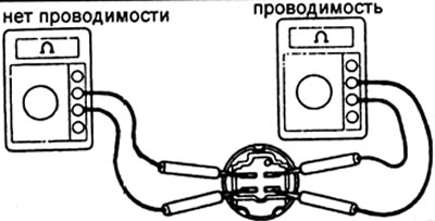
1. Using an ohmmeter, check for continuity between the connector terminals.
If there is continuity, replace the vacuum circuit breaker.
2. Check the operation of the switch.
A) Create a vacuum of 200±50 mm Hg on the switch. Art. (or more).
b) Use an ohmmeter to check for continuity between the switch terminals.
If there is no continuity, replace the switch.
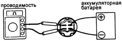
Fuel heater relay
Installation location - relay box in the engine compartment.
1. Checking relay circuits.
A) Check for continuity between terminals "1" And "3".
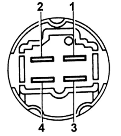
b) Check for continuity between terminals "2" And "4". If the test results are negative, replace the relay.
V) Connect battery power to terminals "1" And "3".
G) Check for continuity between terminals "2" And "4". If there is no continuity, replace the relay.