
Series L
Note: For naturally aspirated engines, ignore the items related to a supercharged engine.
1. Drain the coolant.
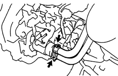
2. Remove the turbocharger cooling water hose.
3. Remove drive belts, fan and water pump pulley.
4. Remove the crankshaft pulley.
5. Remove timing belt cover #1.
6. Set the piston of the first cylinder to the TDC position (compression stroke).
7. Remove the timing belt.
8. Remove the timing pulley.
9. Remove the accelerator drive linkage.
10. Disconnect the boost pressure corrector hose.
11. (For vehicles equipped with air conditioning). Disconnect the idle speed booster vacuum hose when the A/C is turned on.
12. (For engines with a heating controller). Disconnect the coolant hoses from the heat control actuator thermostat.
13. Disconnect the injection pump connectors.
14. Disconnect from TNVD fuel hoses.
15. Removing the high pressure pipes,
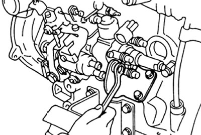
A) Loosen the high pressure tube nuts on the injectors.
b) Loosen the nuts of the high pressure pipes on the injection pump.
V) Remove the four clamps and high pressure tube assemblies.
Note: on a vehicle with a pre-injection device (2L-T) do not damage the pre-injection unit.
Note: When loosening the tubing nuts on the pump, hold the discharge valve fittings with a 14mm wrench.
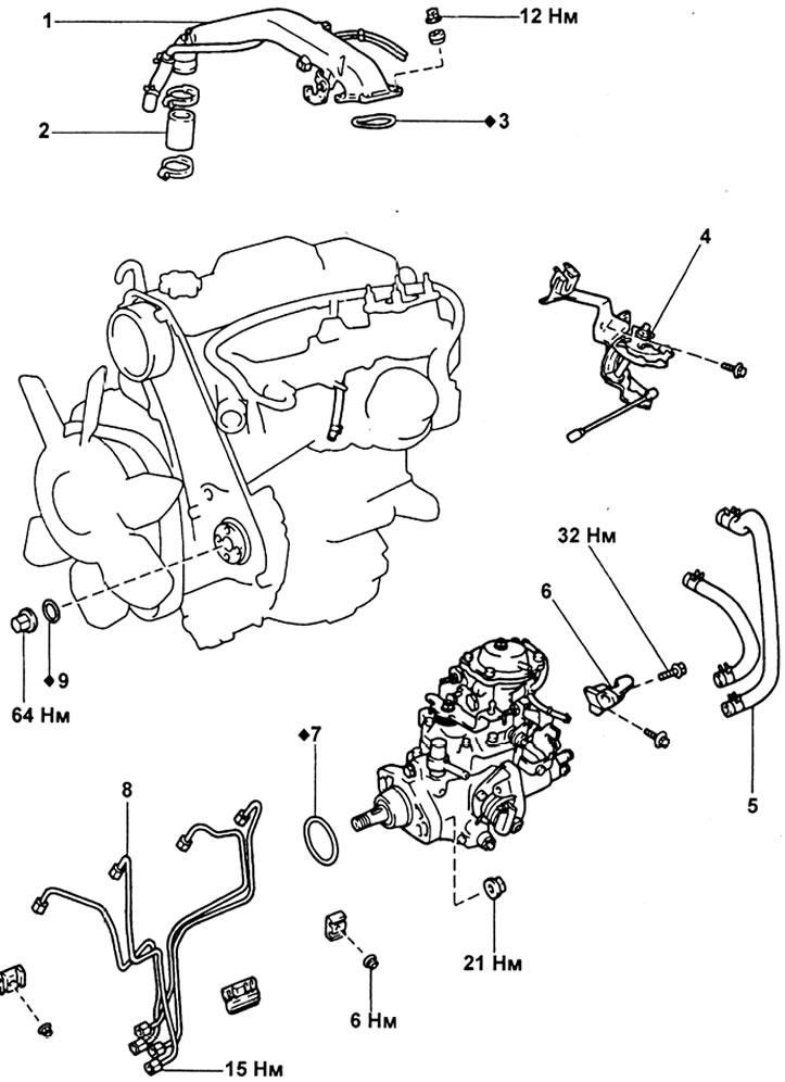
16. Removal of injection pump.
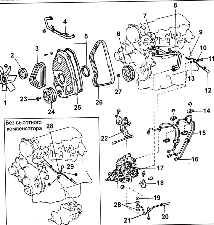
Removal of injection pump (L series engines): 1 - fan, 2 - fan pulley, 3 - drive belt, 4 - turbocharger cooling system hose, 5, 13, 28 - gasket, 6 - injection pump drive pulley, 7 - fuel hose, 8 - heating control actuator hoses, 9 - hose fuel return, 10 - gasket, 11 - M.Z. 25 N.m, 12 - fuel hose, 14 - clamp, 15 - high pressure fuel pipes, 16, 19 - M.Z. 25 N·m, 17 - injection pump, 18 - injection pump support, 20 - fuel supply hose, 21 - fuel supply pipe, 22 - accelerator lever mechanism, 23 - bolt M.Z. 167 N.m, 24 - crankshaft pulley, 25 - timing belt front cover, 26 - timing belt, 27 - M.Z. 64 N.m.
A) Remove the four bolts and remove the pump support.
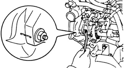
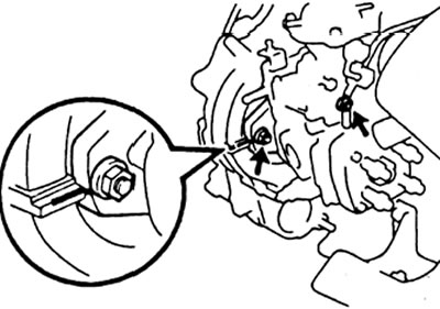
b) Before removing the injection pump, check the alignment of the alignment marks.
If marks are missing, mark your own marks on the pump flange and motor block for later installation.
V) Unscrew the two nuts, remove the injection pump.
Note: Do not hold or carry the pump by the drive lever.
17. Disconnect the remaining fuel lines from the pump.
Engine 1KZ-T
1. (With heating control): Drain the coolant.
2. Remove the intake duct.
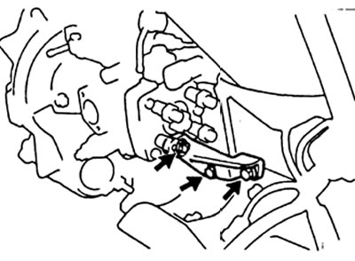
3. Remove an arm and draft of a drive of the lever of TNVD.
4. Remove the high pressure fuel pipes.
5. (On models with air conditioning): Disconnect the vacuum hose of the idle control actuator when turning on the air conditioner
6. Remove the camshaft drive belt.
7. Remove the camshaft drive belt drive sprocket (on the injection pump gear).
8. Removal of injection pump.
Removal of injection pump (engine 1KZ-T): 1 - intake air duct, 2 - air duct hose, 3 - gasket, 4 - brackets and drive rod of the injection pump lever, 5 - cooling system bypass hose (idling speed thermostatic system), 6 - injection pump bracket, 7, 9 - sealing ring, 8 - high pressure fuel pipes.
A) (Engines with preheat control) Disconnect the two thermostat water hoses.
b) Disconnect the fuel cutoff valve connector.
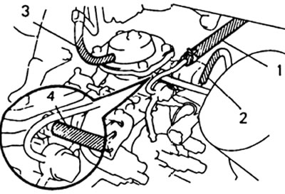
V) Disconnect: fuel hose (1), power limit drive vacuum hose (2), boost corrector vacuum hose (3), height compensator vacuum hose (4) (if installed).
G) While holding the crankshaft from turning, unscrew the nut securing the injection pump drive gear.
d) Remove the three bolts securing the rear injection pump support.
e) Before removing the injection pump, mark the relative position of the injection pump flange and the gear cover
and) Loosen the two nuts securing the injection pump flange.
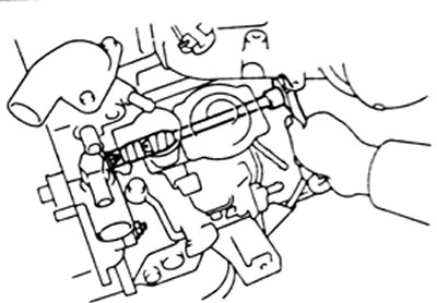
h) Remove the injection pump using a puller.
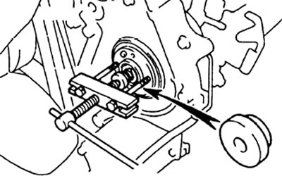
Note: screw the puller bolts to a depth of at least 8 mm; do not move the injection pump by the control lever; do not tilt the injection pump at an angle greater than 45°to the horizontal.
And) Remove the rubber sealing ring.