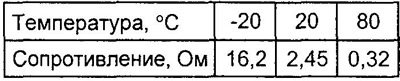
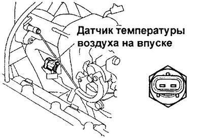
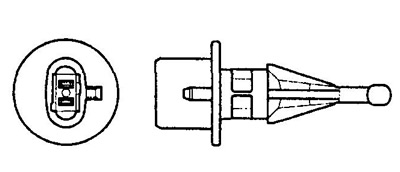
Intake air temperature sensor
Check the resistance at the terminals of the intake air temperature sensor.
EJ-series
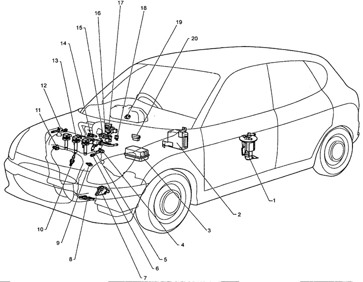
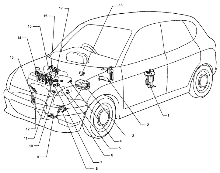
Location of elements of the electronic engine control system (EK-VE Japan models)
1 - fuel pump,
2 - electronic control unit,
3 - relay block,
4 - camshaft position sensor,
5 - nozzle,
6 - fuel knock sensor,
7 - start inhibit switch (models with automatic transmission),
8 - rear oxygen sensor,
9 - coolant temperature sensor,
10 - front oxygen sensor,
11 - crankshaft position sensor,
12 - DWT system valve,
13 - ignition coil,
14 - intake air temperature sensor,
15 - ISC valve,
16 - throttle position sensor,
17 - intake air pressure sensor,
18 - electropneumatic valve,
19 - vehicle speed sensor,
20 - diagnostic connector.
KZ series.
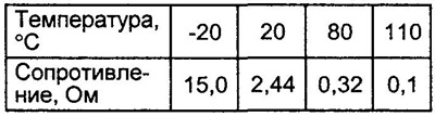
Coolant temperature sensor
Resistance test
Check the resistance between the connector pins.
Note: When immersing the sensor in water, be careful not to get it on the connector. After checking the sensor, wipe off all water from it.
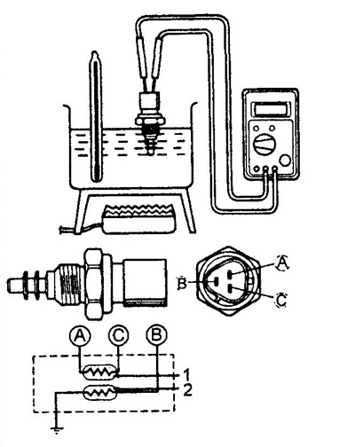
1 - thermistor for the engine control system,
2 - thermistor for the pointer sensor.
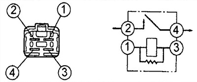
Fuel Pump Relay, Main Injection Relay and Radiator Fan Relay
1. Turn the ignition key to position "ON" and by the presence of sound and vibration, check that the relay is working.
Caution: The relay may be hot after a long period of operation.
2. Measure the resistance between the leads "1" - "3".
- Rated resistance - 74 -117 Ohm
3. Apply battery voltage to terminals "1" - "3" relay and check for continuity between the terminals "2" - "4".
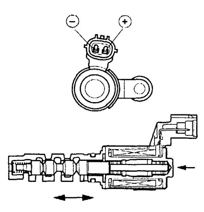
Location of elements of the electronic engine control system (KZ-VE, Japan models).
1 - fuel pump,
2 - electronic control unit,
3 - relay block,
4 - intake air temperature sensor,
5 - electropneumatic valve,
6 - camshaft position sensor,
7 - fuel knock sensor,
8 - start inhibit switch (models with automatic transmission),
9 - oxygen sensor,
10 - coolant temperature sensor,
11 - nozzle,
12 - oxygen sensor,
13 - crankshaft position sensor,
14 - engine ignition coil,
15 - throttle position sensor,
16 - intake air pressure sensor,
17 - ISC valve,
18 - diagnostic connector.
DWT system valve
1. Resistance check.
A) Check the resistance between the connector pins.
- Rated value (at 20°C) - 6.9-7.5 ohms
2. Checking work.
A) Apply battery voltage to the terminals and check the movement of the spool.
Note:
- Make sure the spool is not stuck.
- If the return of the spool is difficult due to contamination or foreign particles, there will be a small leak in the lead line. Ultimately, conditions arise under which a diagnostic code is generated.
EJ-series
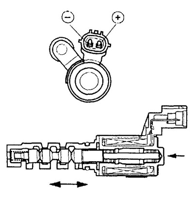
KZ series
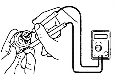
Knock sensor
Make sure there is no continuity between the connector pin and the sensor body.
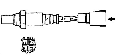
Oxygen sensor
Check the front and rear oxygen sensors.
Measure lead resistance "+V" - "NT".
- Rated resistance (at 20°C) - 11.7 - 14.5 ohms