
Float level
The float level should be checked with it raised (upper) and lowered (lower) condition. A piece of steel rod can be used for the first test. The second check requires a set of feeler gauges from 1.67 to 1.99 mm. The check is carried out as follows:
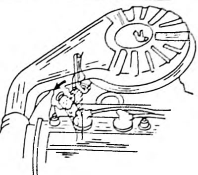
- Turn the carburetor over so that the float lies flat and measure the distance from the bottom edge of the float to the surface of the carburetor cover. Insert a steel rod with a diameter of 7.2 mm (for example a drill rod) into the slot, as shown in Figure 130. The cover gasket must be removed. To adjust, bend the tongue in Figure 130. Check the float level again. The steel rod should enter with resistance and touch the float on one side and the surface of the lid on the other.
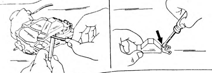
Pic. 130. Adjustment of the upper level of the float, that is, the float rests on the lid. To adjust, bend the tongue (on the right picture)
- For the second check, hold the float as shown in Figure 131 and insert the said feeler gauge between the float needle pin and the jaw on the float. If necessary, to adjust the float level, bend the tongue in Figure 133. After this adjustment, check the first adjustment again. Throttle opening
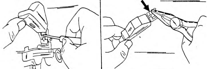
Pic. 131. Adjustment of the lower level of the float, that is, the float is moved away from the lid. To adjust, bend the tongue (on the right picture)
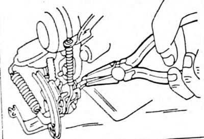
Pic. 132. Bend the stop tongue to adjust the opening of the throttle valve in the primary chamber.
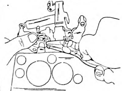
Pic. 133. Bend the stop tongue to adjust the throttle opening of the secondary chamber.
- First screw in the idle speed adjusting screw together with the spring at the bottom of the carburetor. Screw the screw in until it stops, and then unscrew it three turns from this position.
- Place the carburetor flange up and open the throttle valve of the first chamber by turning the lever to the left. The shutter should be positioned exactly along the camera.
- If this is not the case, bend the thrust tongue of the throttle lever, as shown in Figure 132.
- Fully open the throttle valve of the first chamber and with the other hand press the throttle lever of the second chamber to the left so that the throttle valve of the second chamber is at an angle of 80°. If the throttle valve of the second chamber is not positioned correctly, carefully bend the small stop of the throttle lever of the second chamber with pliers, as shown in Figure 133.
Fast idle
- To adjust the fast idle speed, a speed meter is required, which should be connected in accordance with the operating instructions.
- Warm up the engine and turn it off again.
- Remove the air filter.
- Close the connection point of the warm air hose with a plug. If a catalytic converter is installed, the exhaust gas return device must be disconnected. These engines have a thermostat vacuum valve, to which four upward-facing hoses are connected. The second hose from the outside must be disconnected, the connection to the valve must be closed accordingly.
- Hold the throttle slightly open, pull the idle speed cam up and release the throttle while holding the cam.
- Start the engine again without pressing the gas pedal (or without operating the throttle lever) and count (fast idle speed from the speed meter scale. If the rpm is outside 3000±
- 200 rpm, rotate the adjusting screw (1) (pic. 134) until the device readings correspond to the specified value. The radiator fan should not turn on during adjustment.
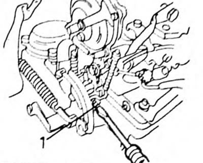
Pic. 134. Adjusting fast idle speed
Adjusting the idle speed
- First check the ease of movement of the air damper.
- Fully screw in the idle mixture adjustment screw on the side of the throttle body without tightening it, and from this position turn it back three turns.
Note: A special wrench is required to turn the idle air mixture adjustment screw. The key pushes through the protective cap and after that you can turn the screw. Under normal conditions, adjusting the idle speed by rotating the throttle stop screw is sufficient.
Idle speed should be adjusted under the following conditions:
- Disconnect the hose from the air filter and close the end of the hose accordingly (insert screw).
- The air filter must be on.
- On a vehicle with a catalyst, disconnect the vacuum hose shown in Figure 135 and close it with a screw.
Pic. 135. Disconnect the vacuum hose and close it with a screw (car with catalyst).
- The engine must be at normal operating temperature.
- The air damper must be fully open.
- All energy consumers must be turned off. The fan should also not turn on.
- All vacuum hoses must be connected.
- The automatic transmission must be set to "N". The ignition timing must be set.
- The float chamber must be filled with fuel (The engine must first run).
- The speed meter must be connected in accordance with the manufacturer's operating instructions.
During the actual adjustment:
- Warm up the engine.
- Rotate the screw (1) in Figure 136 until the following idle speed is established:
- with manual gearbox - 800 rpm
- with automatic transmission - 900 rpm
- Give a little gas and check the idle speed again. If necessary, make other adjustments.
- Measure the CO content in the exhaust gases using a CO meter. To do this, run the engine for 20 seconds at 2000 rpm, wait 1 minute and then take the readings. This work should be done in 3 minutes.
- If the CO content goes beyond 1.0-2.0% on a car without a catalyst or 0-0.5% on a car with a catalyst, gradually turn the mixture adjustment screw (2) in Figure 136 until the CO content returns to normal. If there is no CO meter, set the mixture adjustment screw to the position at which the engine has maximum speed and then rotate the idle speed adjustment screw, bringing the speed to the following values: with a manual transmission 860 rpm with an automatic transmission 960 rpm After Then screw in the mixture adjustment screw so that the engine runs at normal idle speed.
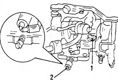
Pic. 136. Location of the idle speed adjustment screw (1) and mixture adjustment screw (2)