



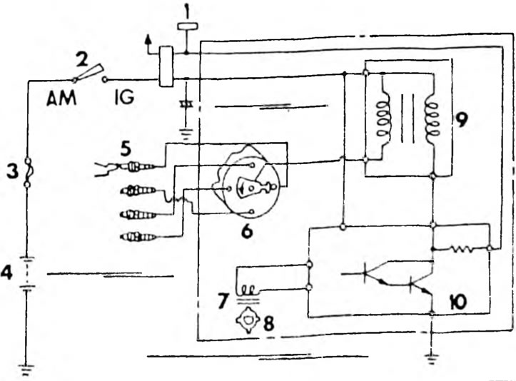
Fig. 146. Ignition system of the 4A-F/FE engine.1. Terminal connection; 2. Ignition switch; 3. Fuse, 30 A; 4. Battery; 5. Spark plugs; 6. Cover and runner of the ignition distributor; 7. Coil; 8. Signal sensor; 9. Ignition coil; 10. Ignition switch.
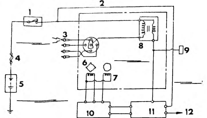
Fig. 147. Ignition diagram of the 3S-FE engine. 1. Ignition switch; 2. Ignition distributor; 3. Spark plugs; 4. Fuse 30A; 5. Battery; 6. Pulse sensor; 7. Coil; 8. Ignition coil; 9. Connection terminal; 10. Electronic control unit; 11. Ignition switch; 12. To the tachometer.
(The text is quoted from the source website: «www.ToyotaMan.ru»)