a) Using a screwdriver, install a new snap ring on one side into the piston boss hole.
b) Gradually heat the piston to a temperature of 80-90°C.
c) Apply a small amount of engine oil to the piston pin and into the piston boss holes.
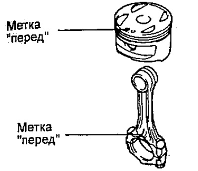
d) Align the "front" marks on the connecting rod piston and install the piston pin.
d) Using a screwdriver, install the second new snap ring on the other side of the piston boss hole.
2. Install the piston rings.
a) Install the expander and two oil scraper ring scrapers.
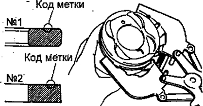
6) Using a piston ring expander, install two compression rings; and the ring marks should be facing upwards, as shown in the figure.
Label code:
2C:
- compression ring #1 - 1R or T1
- compression ring #2 - 2R or 2T
3S-FE, 4S-FE:
- compression ring No.1 - 1N or T
- compression ring #2 - 2N or 2T
4A-FE, 5A-FE, 7A-FE:
- compression ring #2 - 2R or T
c) Install the piston rings in the grooves so that their locks are located as shown in the figure.
Note: Do not align the ring locks.
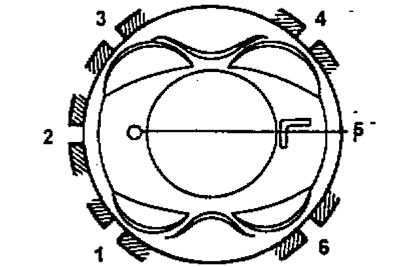
1 - compression ring No.2,
2 - oil scraper ring expander,
3 - upper scraper of the oil scraper ring,
4 - compression ring No.1,
5 - mark "in front" (protrusion),
6 - lower scraper of the oil scraper ring.
3. Install the connecting rod bearing shells.
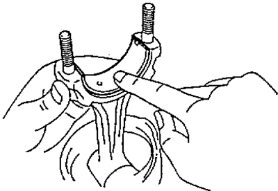
a) Align the bearing shell projection with the recess in the lower connecting rod head and with its cover.
b) Insert the liners into the lower connecting rod head and into the connecting rod cap.