
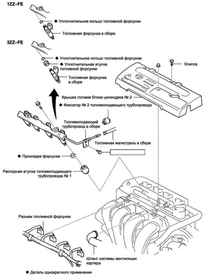
Pic. 2.488. Fuel System Components (1ZZ-FE/ 3ZZ-FE)
Reduce the pressure in the fuel system.
Disconnect the negative battery terminal.
Remove the cylinder bank head cover No. 2.
Removing the fuel supply pipe assembly
Disconnect the retainer No. 2 of the fuel supply pipe.
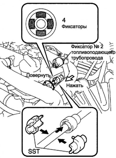
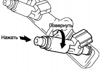
Pic. 2.489. Installing the special tool for removing the fuel line
Using SST 09268-21010, disconnect the fuel line from the fuel supply line (pic. 2.489).
Hold the fuel line fitting with your hand, then install the SST.
Rotate the SST to align the clip inside the fuel line fitting with the beveled part of the SST. Insert the SST into the fuel line fitting.
Hold the SST in the position shown, then push the fuel line fitting in the direction of the SST. Slide the fuel line fitting clamp onto the beveled portion of the SST.
Note. The fuel line clamp is not fixed.
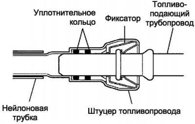
Pic. 2.490. Alignment diagram of SST with fuel line fitting in the direction of the fuel line
Slide the SST with the fuel line fitting in the direction of the fuel line until it clicks, then disconnect the fuel line.
Note. Before performing work, remove dirt and foreign objects from the fitting.
Note. Disconnect the parts carefully so that scoring does not form and foreign particles do not get on the parts, since the fitting has an o-ring that ensures the tightness of the connection with the fuel supply pipeline, which can be damaged.
Note. The work is done using SST. The use of another tool is prohibited.
Note. Do not forcefully bend or twist the nylon tube.
Note. After disconnecting the fuel line, the connected part should be closed with a plastic bag.
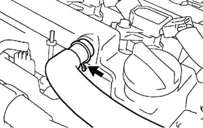
Pic. 2.491. Hose clamp No. 1 of the crankcase ventilation system
Disconnect hose No. 1 of the crankcase ventilation system from the cylinder head cover (pic. 2.491).
Disconnect the 4 fuel injector connectors.
Disconnect the 3 wire harness clamps.
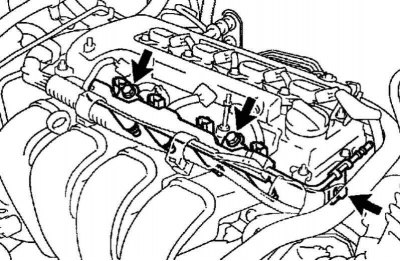
Pic. 2.492. Bolts of fastening of the fuel-supplying pipeline with atomizers
Turn out 3 bolts and remove the fuel-supplying pipeline with atomizers (pic. 2.492).
Note. Remove the fuel supply line carefully so as not to drop the injectors.
Remove the 2 spacers for the No. 1 fuel supply pipe from the cylinder head.
Remove the 4 injector gaskets from the cylinder head.
Removing fuel injectors assy
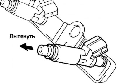
Pic. 2.493. Removing the fuel injector
Remove the 4 fuel injectors from the fuel supply pipe (pic. 2.493).
Installation of fuel injectors assy
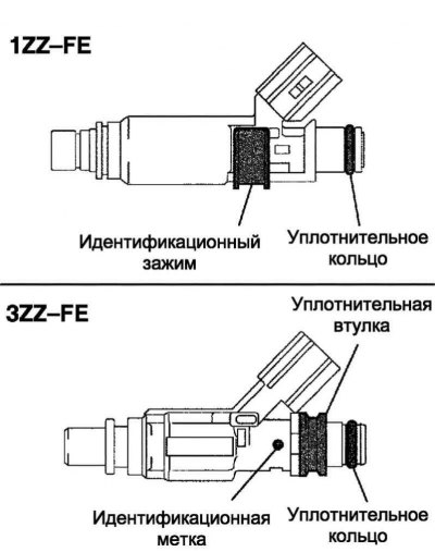
Pic. 2.494. Installing the sealing ring on the injector
Lubricate the O-rings with fuel or spindle oil, then install the O-rings on the injectors (pic. 2.494).
Note. Replace the injector with an injector with the same specifications. See tables below.
For 1ZZ-FE engine
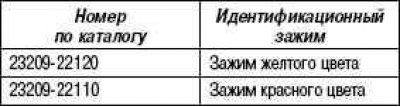
For 3ZZ-FE engine

Pic. 2.495. Fuel injector installation
Apply a thin layer of fuel or spindle oil to the O-ring again, then install the fuel injectors on the right and left sides of the fuel supply pipe (pic. 2.495).
Note. During installation, be careful not to damage or pinch the O-ring.
Make sure the fuel injectors turn without sticking. If the fuel injector does not turn, replace the O-ring.
Installing the fuel supply pipe assembly
Install 4 new gaskets in the cylinder head.
Install the 2 No. 1 fuel line spacers to the cylinder head.
Note. When installing, make sure that the spacers of the fuel supply pipe No. 1 are correctly positioned.
Install the fuel supply pipe with injectors as an assembly, then temporarily tighten the 3 bolts.
Note. When installing the fuel supply line, be careful not to drop the fuel injectors.
Make sure the fuel injectors turn without sticking.
If the fuel injector does not turn, replace the O-ring.
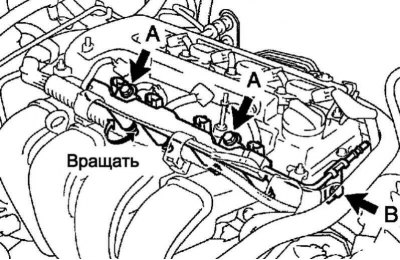
Pic. 2.496. Fuel line bolts
Tighten 3 bolts to specified torque (pic. 2.496).
Tightening torque: 19 Nm for bolt A, 9.0 Nm for bolt B.
Install the 3 wire harness clamps.
Attach 4 fuel injector connectors.
Attach hose No. 1 of the crankcase ventilation system to the cylinder head cover.
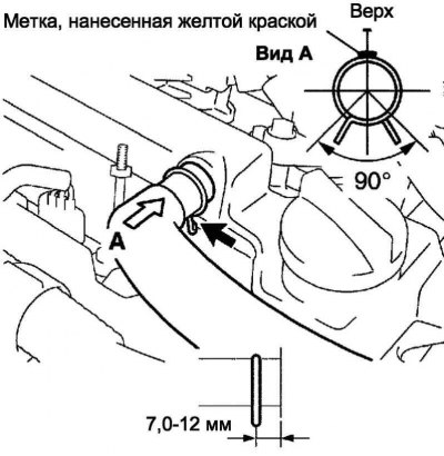
Pic. 2.497. Installing the hose clamp No. 1 of the crankcase ventilation system
Note. Make sure that the paint mark and the hose clamp are at the correct angle when installing (pic. 2.497).
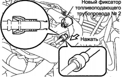
Pic. 2.498. Alignment of the axes of the fitting and the hole in the fuel supply pipeline
Align the axes of the fitting and the holes in the fuel supply pipeline, then insert the fitting into the fuel supply pipeline until the latch clicks (pic. 2.498).
Note. Make sure that the parts to be joined are not damaged or have foreign particles on them.
Note. After assembly, pull on the fuel line or fitting to make sure the connection is secure.
Install a new #2 fuel line retainer.
Connect the negative terminal to the battery terminal.
Tightening torque: 5.4 Nm.
Check for fuel leaks.
Install the cylinder bank #2 head cover.