Checking the fuel pump
Check resistance.
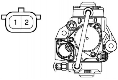
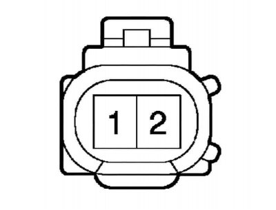
Pic. 2.482. Fuel pump connector
Measure the resistance between the terminals with an ohmmeter (pic. 2.482).
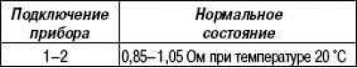
Verification conditions

If the result is not normal, the fuel priming pump should be replaced.
Checking the fuel injector assembly
Check resistance.
Pic. 2.483. Connector pins
Measure the resistance between the terminals with an ohmmeter (pic. 2.483).
Verification conditions
If the result is not normal, replace the injector assembly.
Check Common Rail Fuel System Assembly
Check the resistance of the fuel pressure sensor.
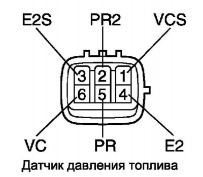
Pic. 2.484. Connector pins
Measure the resistance between the terminals with an ohmmeter (pic. 2.484).
Verification conditions
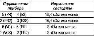
If the result is not normal, replace the Common Rail fuel system assembly.
Pressure reducing valve resistance test
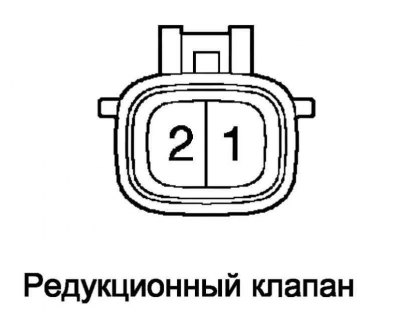
Pic. 2.485. Connector pins
Measure the resistance between the terminals with an ohmmeter (pic. 2.485).
Verification conditions
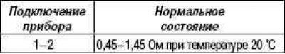
If the result is not normal, replace the Common Rail fuel system assembly.
Checking the fuel heater assembly
Check resistance.
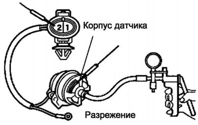
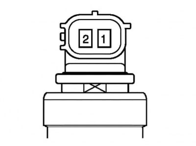
Pic. 2.486. Blower connection
Create a vacuum of 34.7±5.3 kPa in the electrovacuum switch (pic. 2.486).
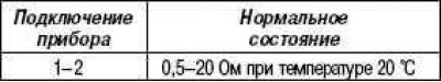
Use an ohmmeter to measure the resistance between terminal 2 and the switch housing.
Verification conditions
If the result is not normal, replace the fuel heater assembly.
Checking the sensor for the presence of water in the fuel filter
Check resistance.
Pic. 2.487. Connector pins
Measure the resistance between the terminals with an ohmmeter (pic. 2.487).
Normal condition:
- when the float is raised - less than 1 ohm.
- when lowering the float - 10 kOhm or more.
If the result is not normal, replace the fuel filter water sensor.
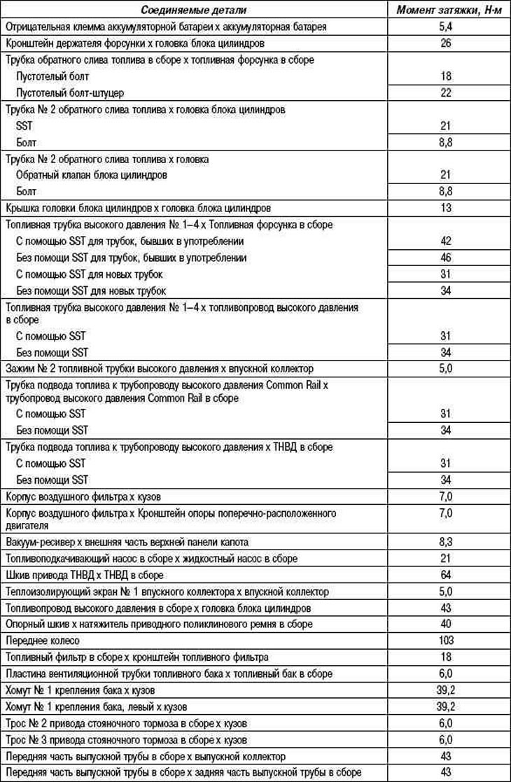
Table 2.30. Technical data for inspection and adjustment work (1CD-FTV)
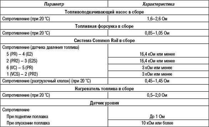
Table 2.32. Rated tightening torques (1CD-FTV)