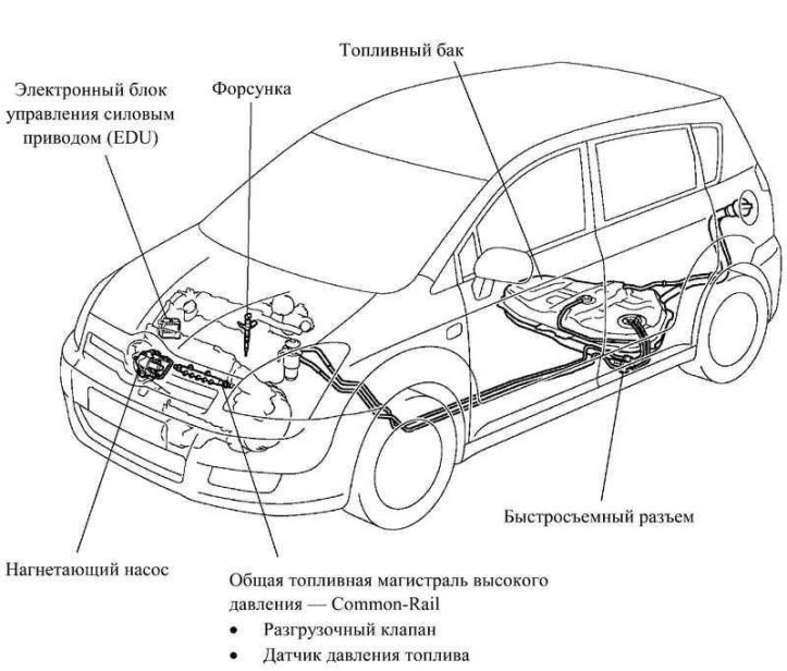
Pic. 2.82. Fuel system of a car with a 1CD-FTV engine
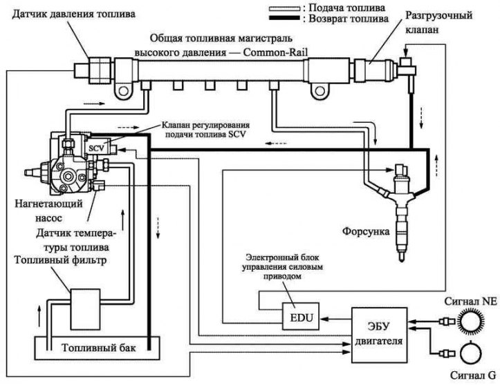
Pic. 2.83. 1CD-FTV engine fuel system block diagram
To improve maintainability, the fuel line is connected to the fuel hose using a quick connector.
Similar to the previous model, the new engine uses a common rail injection system (common-rail).
Differences from previous models
To increase power and reduce exhaust toxicity at high speeds, the new Corolla Verso model has a common rail injection system (Common-Rail), providing high pressure in the fuel system. In this regard, the following changes have been made to the design of the fuel system:
- modified common fuel rail (Common-Rail), pressure pump and nozzles;
- the pressure limiter is excluded;
- relief valve installed.
Common high pressure fuel line - Common-Rail
In this system, the high pressure fuel generated by the charge pump is in the common rail. The engine ECU sends signals to the injectors through the powertrain ECU to control when the injection starts and how much fuel is injected.
Delivery pump
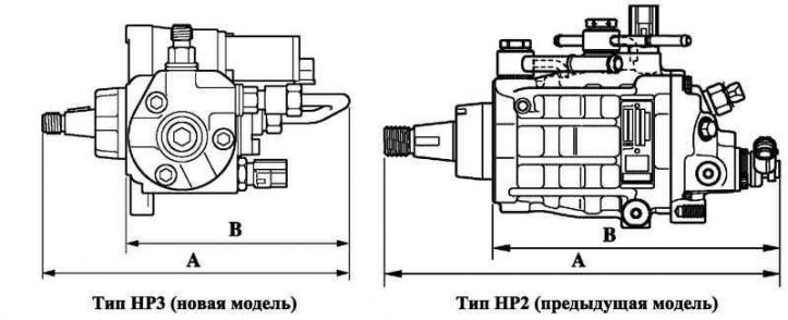
Pic. 2.84. Injection pumps of current and previous models
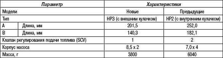
Instead of traditional HP2 type 4-plunger injection pump (with internal cam) the 1CD-FTV engine has a 2-plunger NRZ with an external cam. As a result, the pump has become more compact, its overall length has been reduced (pic. 2.84).
Design features
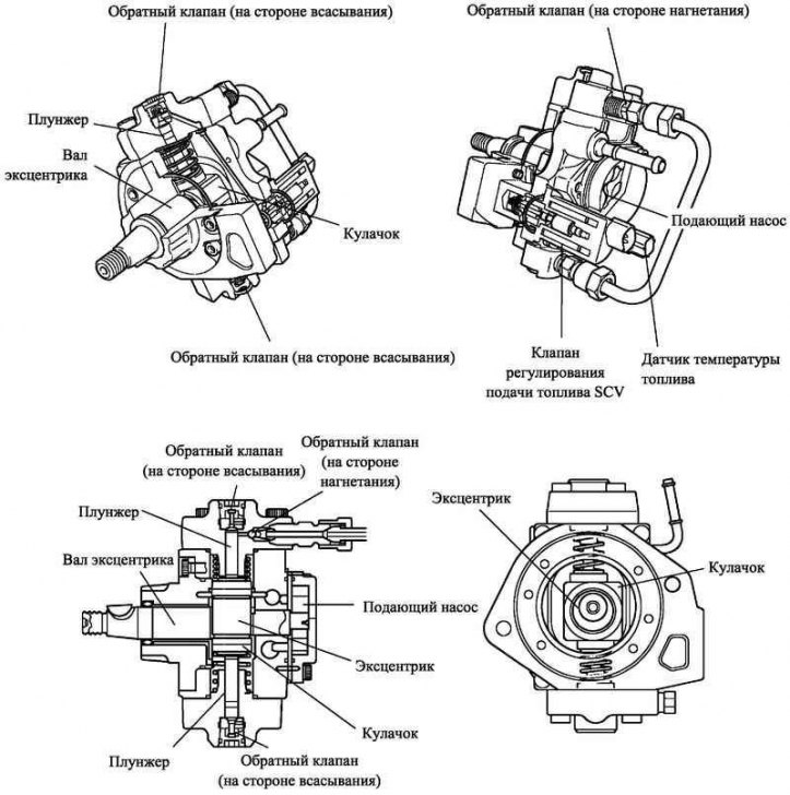
Pic. 2.85. The design of the injection pump
The charge pump consists of an eccentric shaft, a cam, two plungers, four check valves and a fuel control valve (SCV), fuel temperature sensor and feed pump.
The cam actuates two plungers located opposite each other.
Principle of operation
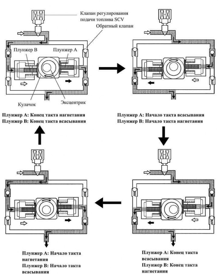
Pic. 2.86. Scheme of operation of the pressure pump
When the eccentric shaft is turned, the cam moves plunger A to the right, as shown in Figure 2.86. Plunger B (opposite plunger A) under the action of the spring also moves to the right. As a result, plunger B sucks in, and plunger A displaces fuel into the line.
Common high pressure fuel line - Common-Rail
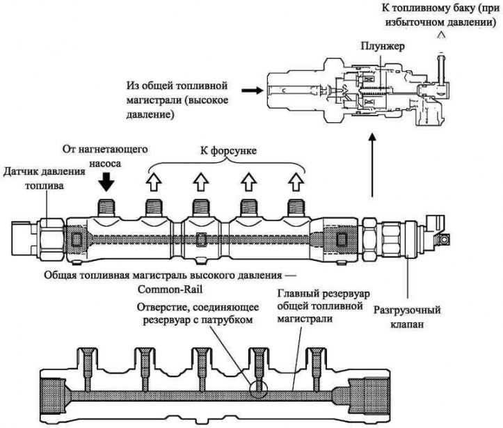
Pic. 2.87. Common high pressure fuel line
The common high pressure fuel line serves as a reservoir for the fuel pumped by the high pressure pump. The common fuel line is equipped with a fuel pressure sensor and an unloader valve that regulates the fuel pressure in the common fuel line.
The Common-Rail main consists of a main tank from which five nozzles exit. The reservoir is connected to the nozzles with holes with a diameter of 1 mm, damping pressure fluctuations in the fuel system.
The plunger in the relief valve opens and closes according to control signals from the power drive electronic control unit (EDU), thus regulating the pressure in the common fuel line. In addition, in the event of an accident, a pressure relief function is provided.
Maintenance recommendation
The fuel pressure sensor has a sealing area (plastically deformed when the sensor is installed), which ensures the tightness of the connection between the sensor and the fuel line; the sealing area cannot be reused once the sensor has been removed.
When replacing parts that affect the alignment of the assembly connections, install a new high pressure fuel pipe. Below is a list of such parts.
A new high pressure fuel pipe is installed when replacing: nozzles, common fuel line, cylinder head.
A new fuel supply pipe to the common fuel line is installed when replacing: the injection pump, the common fuel line, the cylinder block, the coolant pump, the cylinder head.
Nozzle
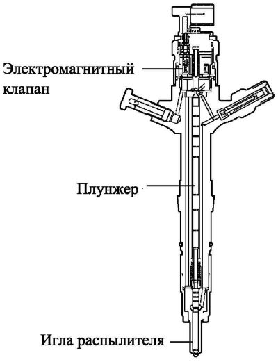
Pic. 2.88. Nozzle design
The design of the nozzle includes: a spray needle, a plunger and a solenoid valve.
Each injector is marked with its characteristics in the form of an adjustment value and a QR code.
The marking of the injectors contains various information, such as the model code and correction values for the electronic control unit, which sets the volume and moment of the start of fuel injection.
Maintenance recommendation
When installing a new engine ECU, the correction values of all 4 injectors must be written into it using the microprocessor tester P. When installing new injectors, their correction values must be entered into the engine ECU. The control unit will correctly calculate the corrections, and the accuracy of the fuel supply after replacing the nozzle will not decrease.
To read the QR code, you need a special scanner that is not used by Toyota dealers.
The QR code is a graphic combination of square cells, with the help of which a large amount of information is encoded.
In the QR code, information is encrypted in various forms (numeric, alphanumeric, kanji, kana and binary). This type of encoding allows you to encrypt up to 7089 characters.
QR code (two-dimensional) contains data vertically and horizontally, whereas a barcode contains information in only one direction. Hence the QR code (two-dimensional) is a much more capacious means of recording information than a barcode.
Principle of operation
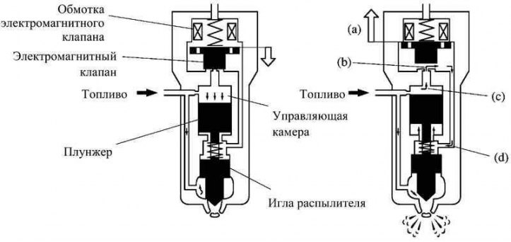
Pic. 2.89. The principle of operation of the fuel injector
- a. When an electric current enters the coil of the solenoid valve, the core is pulled up.
- b. The needle valve of the control chamber opens a channel through which fuel begins to flow.
- c. The pressure in the control chamber drops.
- d. At the same time, fuel through the hole enters under the plunger and lifts it up (response time is reduced).
- e. As a result, the atomizer needle associated with the plunger rises and fuel is injected.
Table 2.13. Specifications of the delivery pumps (1CD-FTV engine)