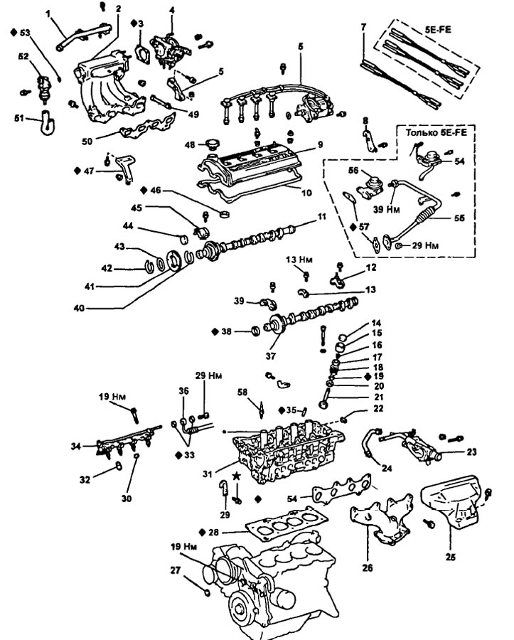
Dismantling of a head of the block of cylinders (5E-FE) 1 - air duct; 2 - intake manifold; 3 - gasket; 4 - throttle body; 5 - bracket for the upper part of the intake manifold; 6 - distributor assembly with high-voltage wires; 7 - vacuum hose; 8 - engine lifting bracket No. 2; 9 - cylinder head cover; 10 - gasket; 11 - intake camshaft; 12 - bearing cover No. 4 of the camshaft; 13 - bearing cover No. 3 of the camshaft; 14 - adjusting washer; 15 - pusher; 16 - crackers; 17 - spring plate; 18 - valve spring; 19 - oil scraper cap; 20 - support washer; 21 - valve; 22 - segment plug; 23 - thermostat housing; 24 - coolant bypass hose; 25 - exhaust manifold heat shield; 26 - exhaust manifold. 27 - cover No. 3 of the timing belt; 28—cylinder head gasket; 29 - engine lift bracket N91; 30 - insulator; 31 - cylinder head; 32 - spacer sleeve; 33 - gasket; 34 - fuel manifold assembly with injectors; 35 - valve guide sleeve; 36 - fuel supply hose; 37 - exhaust camshaft; 38 - stuffing box; 39 - bearing cover No. 1 of the camshaft; 40 - leaf spring of the camshaft gear; 41 - auxiliary gear camshaft; 42 - retaining ring; 43 - spring washer; 44 - plug of the intake camshaft; 45 - bearing cover No. 2 of the camshaft; 46 - gasket; 47 - intake manifold bracket; 48 - oil filler cap; 49 - hose of the crankcase ventilation system; 50 - gasket; 51 - air bypass valve for exhaust; 52- air bypass valve for exhaust (ACV); 53 - ring seal; 54 - vacuum modulator of the exhaust gas recirculation system; 55 - pipe of the exhaust gas recirculation system, assembly; 56 - exhaust gas recirculation valve; 57 - gasket.
Removing the cylinder head
1. Drain the coolant.
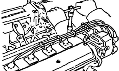
2. Remove the distributor together with high voltage wires.
- A) Disconnect the high voltage wires at the rubber caps.
Note: do not stretch the wires. Pulling or bending wires can cause them to break internally.
- b) Turn away a bolt of fastening of holders of wires.
- V) Disconnect the two connectors.
- G) Unscrew the two clamping bolts and remove the distributor.
- d) Remove the distributor housing O-ring.
3. Turn away spark plugs.
4. Disconnect the vacuum hoses.
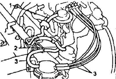
- A) (Models with automatic transmission) Disconnect the following hoses:
- Vacuum hose from throttle actuator (1).
- Vacuum hose from EGR valve (2)
- Three vacuum hoses from the vacuum modulator of the OT recirculation system (3).
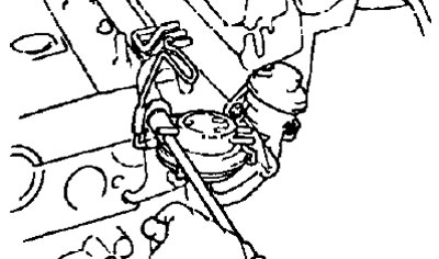
- b) Disconnect the vacuum hose from the fuel vapor accumulator.
5. Remove the EGR pipe, vacuum modulator and EGR valve.
- A) Loosen the union nut of the tube and unscrew the bolt, two nuts and remove the exhaust gas recirculation tube.
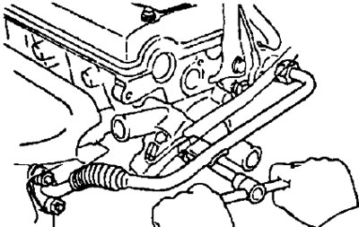
- b) Remove the EGR vacuum modulator and its bracket by removing the bolt.
- V) Loosen the two nuts and remove the EGR valve and gasket.
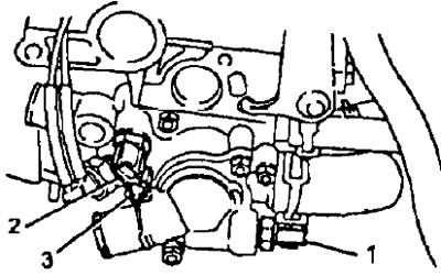
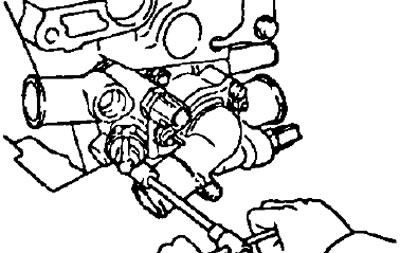
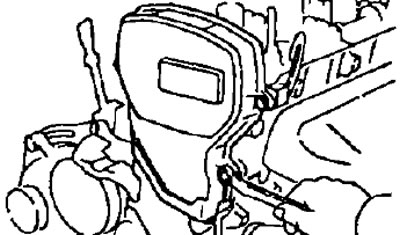
6. Remove the thermostat housing.
- A) Disconnect the following connectors:
- Sensor connector - switch for coolant temperature (to the electric fan drive of the cooling system) (1).
- Coolant Temperature Sensor Connector (2).
- Coolant temperature gauge sensor connector (3).
- (Models with automatic transmission) Coolant temperature switch sensor connector.
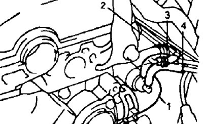
- b) Disconnect the following hoses:
- Coolant Inlet Hose (1).
- Heater outlet hose (2).
- coolant bypass hose (3)
- Two vacuum hoses of a thermally controlled pneumatic valve (4)
- V) Loosen the bolt, two nuts, and remove the EGR valve and gasket.
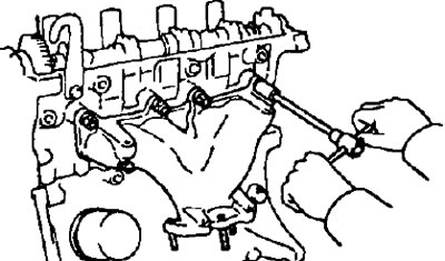
7. Remove the exhaust manifold.
- A) Remove the three bolts and remove the heat shield.
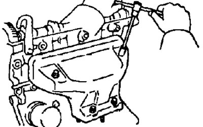
- b) Remove the exhaust manifold and gasket by removing the six nuts.
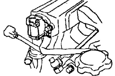
8. Remove the air bypass valve to the outlet.
- A) Disconnect the valve connector.
- b) Disconnect the air duct.
- V) Disconnect two bolts, wire "grounding" and an air bypass valve to the outlet.
- G) Remove the o-ring from the valve.
9. Remove the throttle body.
10 Remove the fuel manifold and injectors.
11 Remove the air tube by removing the two screws.
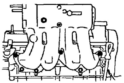
12. Remove the intake manifold.
- A) Remove two bolts, nut and manifold bracket.
- b) Remove three bolts, three nuts and remove the intake manifold.
13. Remove the cylinder head cover
- A) Remove the oil filler cap.
- b) Unscrew the five nuts - covers and remove the sealing washers.
- V) Remove the cylinder head cover and gasket.
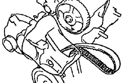
14. Remove the #2 timing belt cover and gasket by removing the four bolts.
15. Remove the alternator drive belt by loosening the axle bolt nut and adjusting bolt.
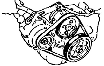
16. Remove #3 timing belt cover from #1 timing belt cover.
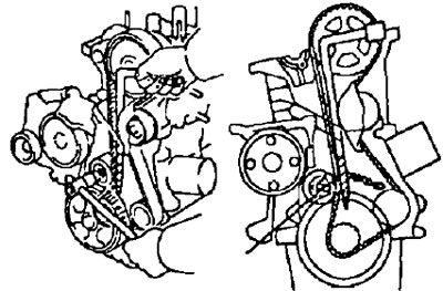
17. Remove the timing belt from the crankshaft sprocket
Note: When reusing the timing belt, mark the timing belt and camshaft sprocket.
- A) Loosen the idler pulley mounting bolt and push the tensioner pulley to the left as far as possible, and then temporarily tighten it.
Note: Do not damage the timing belt.
- b) Remove the timing belt from the camshaft sprocket.
18. Remove the intermediate pulley by unscrewing the bolt.
Note.
- Lock the timing belt so that it does not move.
- Be careful not to drop anything inside.
- Protect the belt from oil, water and dust.
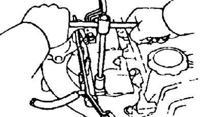
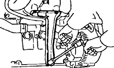
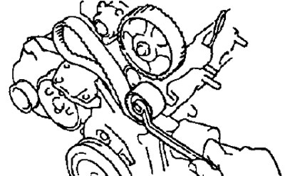
19. Holding the camshaft with one wrench, unscrew the pulley mounting bolt with another wrench and remove the camshaft sprocket.
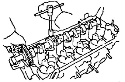
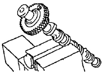
20. Remove the intake and exhaust camshafts. Note: Since the end play of the camshaft is very small, it is necessary to keep the shaft in a horizontal position when removing it, to prevent jamming and / or damage to the shaft, for this it is necessary to follow the dismantling procedure below.
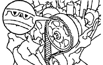
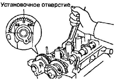
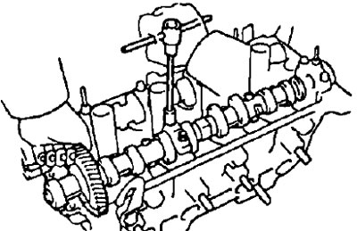
- A) Install the intake camshaft as follows. so that the hole for the technological bolt of the gears of the intake camshaft is on top (as shown in the picture).
Note: In this position, the lugs on the intake camshafts of cylinders #2 and #4 act on the valve lifters to help raise the exhaust camshaft smoothly and evenly.
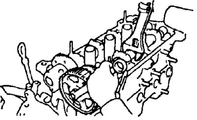
- b) Remove four bolts and remove bearing caps #1 and #2.
- V) Remove the intake camshaft plug and oil seal.
- G) Attach the intake camshaft sub gear to the main gear with a service bolt.
- Recommended process bolt:
- diameter — 6 mm
- thread pitch - 1.0 mm
- bolt length - 16-20 mm
Note: When removing the camshaft, make sure that this operation neutralizes the torsional force of the auxiliary gear leaf spring.

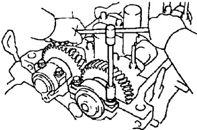
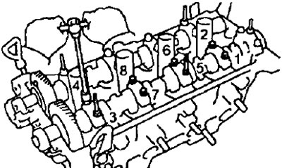
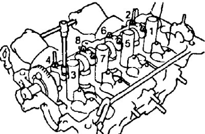
- d) Evenly loosen and remove the eight bearing cap bolts in several passes in the sequence shown in the figure.
- e) Remove the four bearing caps and exhaust camshaft.
Note: If the camshaft does not remove straight and horizontally, re-fasten the bearing cover No. 3 with two bolts, and then loosen the bearing cover bolts one by one, pull the camshaft by the gear.
Note: Do not attempt to remove the camshaft with a tool.
- and) Evenly loosen and remove the eight intake camshaft bearing cap bolts in several passes as shown.
- h) Remove these four bearing caps and intake camshaft.
Note:
- If the camshaft does not come off straight and horizontally, re-attach bearing cover No. 3 with two bolts, and then loosen the bearing cover bolts one by one, pull the camshaft by the gear.
- Do not attempt to remove the camshaft with a tool.
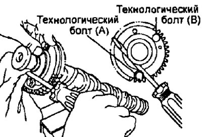
21. Remove the intake camshaft.
- A) Install the hex section of the camshaft in a vise.
Note: Do not damage the camshaft.
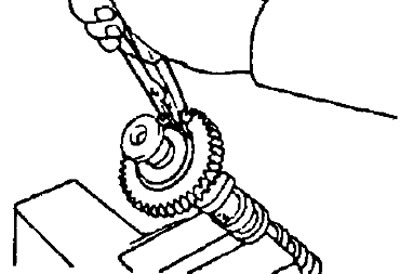
- b) Insert process bolt (A) into the camshaft auxiliary gear hole.
- V) Use a screwdriver to turn the auxiliary gear clockwise and remove the service bolt (IN).
Note: Do not damage the camshaft.
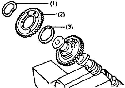
- G) Remove the retaining ring with pliers.
- d) Remove: spring washer (1),camshaft auxiliary gear (2), leaf spring (3).
22. Remove the cylinder head.
- A) Using an 8mm hex socket wrench, evenly loosen and remove the ten cylinder head bolts in several passes in the sequence shown.
Note: If the bolts are loosened incorrectly, the cylinder head may be deformed or cracked.
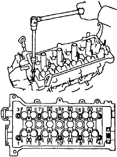
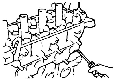
- b) Remove the cylinder head from the guide pins on the cylinder block and lay it on a workbench with wooden blocks underneath.
Note: if the block head is difficult to remove, you can use a powerful screwdriver, inserting it into the gas joint, as shown in the figure. However, take care not to damage the surfaces of the head and block, as well as the head gasket.