
Note: check and adjust the clearance in the valve drive on a cold engine
1. Disconnect the crankcase ventilation hoses from the cylinder head cover.
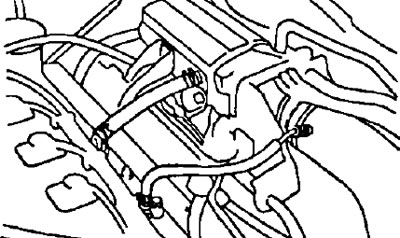
2. Disconnect the engine wiring harness from the intake manifold.
3. Disconnect the high voltage wires from the spark plugs.
Note: Stretching or bending the actuator may cause internal damage to the actuator.
4. Remove the cylinder head cover
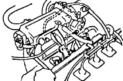
- A) Remove the oil filler cap.
- b) Loosen the five nuts and remove the sealing washers.
- V) Remove the cylinder head cover and gasket.
Note: Install the seals in reverse order so that they are in their original positions when installing. This will reduce the chance of oil leakage due to seal reuse.
5. Install the piston of cylinder No. 1 and TDC of the compression stroke.
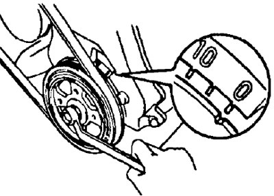
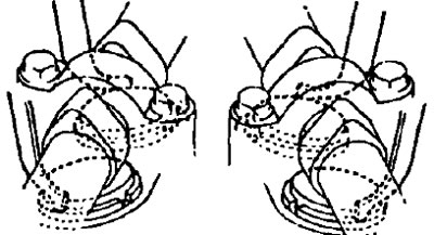
- A) Rotate the crankshaft pulley and align its mark with the alignment mark "ABOUT" on cover #1 of the timing belt.
- b) Check that the Ns1 cylinder tappets are free and the No.4 cylinder tappets are tight. If not, turn the crankshaft one turn (360°) and align the label as above.
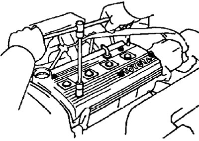
6. Check valve clearance
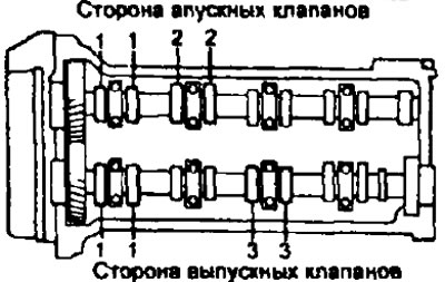
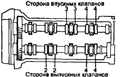
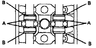
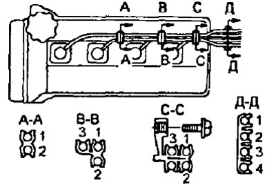
- A) Check the clearance in the actuator of the valves indicated in the figure.
- Using a feeler gauge, measure the clearance between the tappet and camshaft.
- Record your valve clearance measurements. These will be used later to determine the required shim when replacing.
- Valve clearance (cold engine):
- inlet - 0.15-0.25 mm
- graduation - 0.31-0.41 mm
- b) Rotate the crankshaft one revolution (360°) and align the labels as above.
- V) Measure the clearance in the drive of the valves indicated in the figure.
7. Adjust the valve clearance.
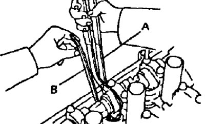
- A) Remove the adjusting washer. Rotate the crankshaft so that the cam lobe is up.
- Set the pusher mark so that the shim can be removed with a small screwdriver.
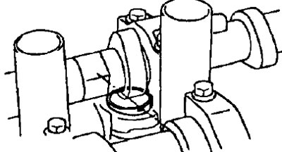
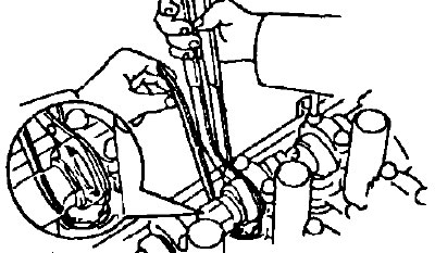
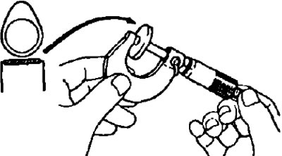
- Using the special tool press the pusher and place the special tool (IN) between the camshaft and pushrod. Remove special tool (A).
Notes:
- Install special tool (A) to any of the locations marked A and B in the figure.
- For easy removal of the shim, install the special tool (IN) on the tappet so that there is enough space to remove the shim.
- Remove the shim using a small screwdriver and a magnetic bar.
- b) Determine the size of the new shim using the following method:
- Using a micrometer, measure the thickness of the removed shim
- Calculate the thickness of the new shim so that the valve clearance is within the specified values.
- The thickness of the removed shim - T
- Measured valve clearance - A
- New shim thickness - N
- inlet — N=T+ (A-0.20 mm)
- graduation - N \u003d T + (A-0.36 mm)
- Select a new shim with a thickness as close as possible to the design value.
Note: shims have 17 sizes (thickness values) from 2.50 mm to 3.30 mm through 0.05 mm.
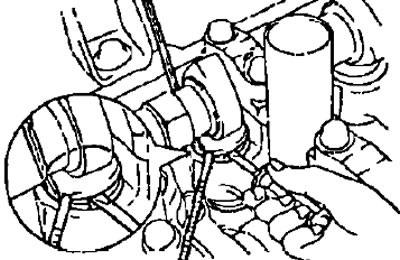
- V) Install a new shim
- Install a new shim in the tappet Using the special tool (A), press the pusher and remove the special tool (IN).
- G) Recheck valve clearance
8. Install the cylinder head cover.
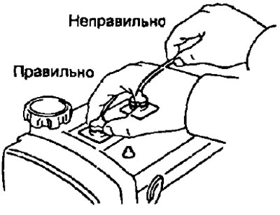
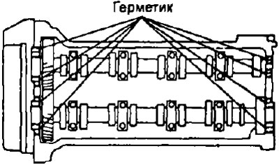
- A) Remove the old sealing material and apply sealant to the cylinder head as shown.
- 6) Install the gasket and then the cylinder head with five sealing washers
- Tightening torque - 7 Nm
- V) Install the oil filler cap.
9. Connect the high voltage wires by tightening the bolt securing the high voltage wire holders to the cylinder head cover.
10. Install the engine wiring harness and its protection with a bolt.
11. Connect the hoses of the crankcase ventilation system.