
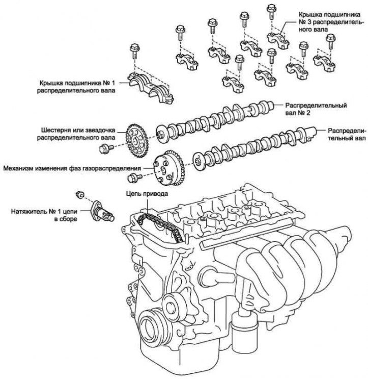
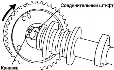
Pic. 2.157. Camshaft components
Remove the cylinder head cover.
Set the No. 1 cylinder piston to TDC on the compression stroke.
Removing the camshaft No. 2
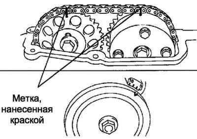
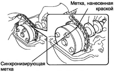
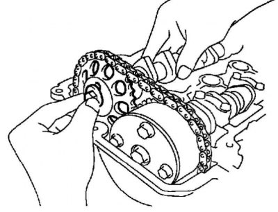
Pic. 2.158. Places for applying queens on the chain and camshaft drive gears
Mark chain and camshaft drive gears (pic. 2.158).
Remove the 2 nuts, then remove the chain tensioner.
Attention! It is forbidden to rotate the crankshaft if the chain is not tensioned with the tensioner.
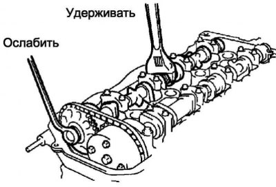
Pic. 2.159. Loose camshaft timing clutch bolt
While holding the hex part of the camshaft with a wrench, loosen the camshaft timing clutch mounting bolt (pic. 2.159).
Note. Be careful not to damage the valve lifters.
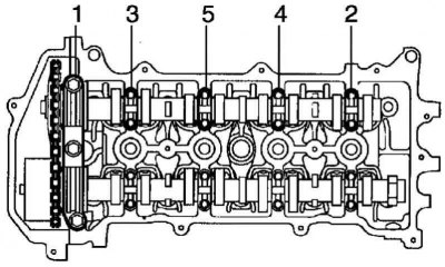
Pic. 2.160. The procedure for loosening the bearing cap bolts
In several steps evenly loosen and unscrew 11 bolts, acting in the sequence shown in Figure 2.160, then remove 5 bearing caps.
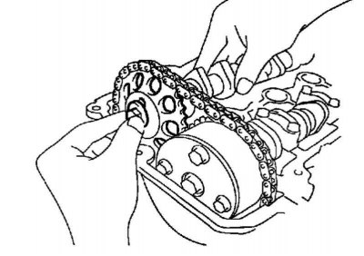
Pic. 2.161. Removing the camshaft drive gear
Remove the camshaft drive gear as shown in Figure 2.161.
Removing the camshaft
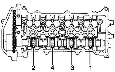
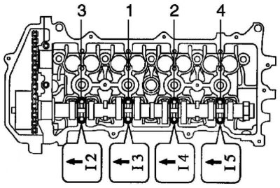
Pic. 2.162. The procedure for loosening the bearing cap bolts
In several steps evenly loosen and turn out 8 bolts, acting in the sequence shown in Figure 2.162, then remove 4 bearing caps.
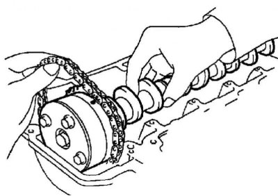
Pic. 2.163. Removing the camshaft
While holding the chain with your hand, remove the camshaft and camshaft timing clutch (pic. 2.163).
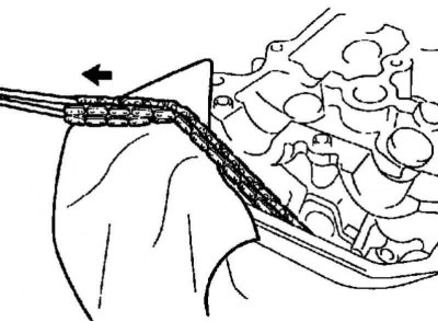
Pic. 2.164. Chain fastening
Fasten the chain with wire, as shown in Figure 2.164.
Note. Make sure that no foreign objects get inside the timing chain cover.
Checking the camshaft synchronizing clutch
Check if the camshaft synchronizing clutch is blocked.
Clamp the camshaft in a vise, then make sure the timing clutch is locked.
Note. Care must be taken not to damage the camshaft.
Remove the lock pin.
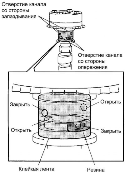
Pic. 2.165. Adhesive tape installation diagram
Close 4 openings of the oil channels on the camshaft journal with adhesive tape, as shown in Figure 2.165.
Note. The two oil passage holes on the advance side are located in the grooves of the camshaft. Close one of the channels with a rubber stopper.
Pierce the tape from the lead channel side and the retard channel side from the opposite side of the groove.
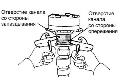
Pic. 2.166. Compressed air supply
Feed into two open channels (advance side and retard side) compressed air at a pressure of about 150 kPa (pic. 2.166).
Attention! Cover the openings of the channels with rags to prevent oil splashing.
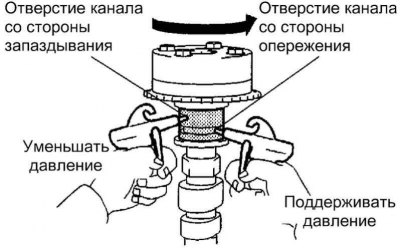
Pic. 2.167. Checking the Synchronizing Clutch
Make sure that when the air pressure in the retard channel decreases, the camshaft synchronizing clutch turns in the advance direction (pic. 2.167).
Note. If the locking pin is removed, the camshaft synchronizing clutch rotates in the advanced direction.
When the camshaft synchronizing clutch reaches the position corresponding to the maximum advance, stop the compressed air supply to the lag side channel, then stop the compressed air supply to the advance side channel.
Attention! If the compressed air supply to the advance side duct is stopped before the compressed air supply to the retard side duct is stopped, the camshaft synchronizing clutch may unexpectedly turn to the retard side. This often leads to breakage of the locking pin.
Check if the synchronizing clutch turns smoothly.
Rotate the camshaft synchronizing clutch several times within the rotation range without reaching the most retarded position, then check if it rotates smoothly.
Attention! Turn the coupling by hand without supplying compressed air.
Check if the clutch locks in the most retarded position.
Make sure the camshaft timing clutch is locked in the most retarded position.
Removing the camshaft timing clutch
Clamp the camshaft in a vise, then make sure the timing clutch is locked.
Attention! Care must be taken not to damage the camshaft.
Close 4 openings of the oil channels on the camshaft journal with adhesive tape, as shown in Figure 2.165.
Note. Two openings of the oil channels on the advance side are located in the grooves of the camshaft. Close one of the channels with a rubber stopper.
Pierce the tape from the lead channel side and the retard channel side from the opposite side of the groove.
Feed into two open channels (advance side and retard side) compressed air at a pressure of about 150 kPa (pic. 2.166).
Attention! Cover the openings of the channels with rags to prevent oil splashing.
Make sure that when the air pressure in the retard channel decreases, the camshaft synchronizing clutch rotates in the advance direction.
Note. If the locking pin is removed, the camshaft synchronizing clutch rotates in the advanced direction.
When the camshaft synchronizing clutch reaches the position corresponding to the maximum advance, stop the compressed air supply to the lag side channel, then stop the compressed air supply to the advance side channel.
Attention! If the compressed air supply to the advance side duct is stopped before the compressed air supply to the retard side duct is stopped, the camshaft synchronizing clutch may unexpectedly turn to the retard side. This often leads to breakage of the locking pin.
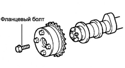
Pic. 2.168. Synchronizing clutch bolt
Turn out a bolt of fastening and remove the synchronizing coupling of a camshaft in gathering (pic. 2.168).
Note. Do not remove the 4 remaining bolts.
Note. When reusing the camshaft synchronizing clutch, you must first release the locking pin, then install the clutch.
Installing the camshaft timing clutch
Install the camshaft synchronizing clutch onto the camshaft without inserting the pin into the groove.
Pic. 2.169. Installing the Synchronizing Clutch
Turn the synchronizing clutch to the left, as shown in Figure 2.169, pressing it slightly towards the camshaft. Keep pressing until the pin enters the groove.
Attention! Do not rotate the synchronizing clutch in the direction of delay (right).
Make sure there is no play between the synchronizing clutch and the camshaft.
Tighten the mounting bolt, fixing the camshaft synchronizing clutch. Tightening torque: 54 Nm.
Make sure the synchronizing clutch can rotate in the retarded direction (right) and locked in the most retarded position.
Installing the camshaft
Pic. 2.170. Timing chain installation camshaft clutch
Put the chain on the camshaft synchronizing clutch, aligning the links with the label with the synchronizing marks on the camshaft gears, as shown in Figure 2.170.
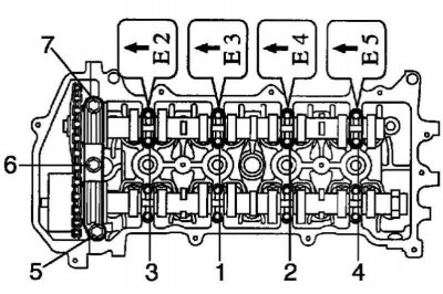
Pic. 2.171. The order of tightening the bolts of the camshaft bearing caps
Check up, whether labels which have to be turned to a forward part of the engine, and numbers of covers are correctly located, then tighten bolts in the sequence specified in drawing 2.171. Tightening torque: 13 Nm.
Installing the camshaft No. 2
Pic. 2.172. Installing the camshaft No. 2
Install the No. 2 camshaft in the cylinder head, aligning the paint mark with the mark on the camshaft drive gear (pic. 2.172).
Pic. 2.173. Baiting of a bolt of fastening of a leading gear wheel of a camshaft
Install the camshaft drive gear bolt (pic. 2.173).
Pic. 2.174. The order of tightening the bolts for fastening the camshaft bearing caps No. 2
Check up, whether labels which should be turned to a forward part of the engine, and numbers of covers are correctly located, then tighten bolts in the sequence specified in drawing 2.174. Tightening torque: 13 Nm.
Install bearing cap #1. Tightening torque: 23 Nm.
While holding the camshaft hex with a wrench, tighten the camshaft drive gear bolt. Tightening torque: 54 Nm.
Note. Be careful not to damage the valve lifters.
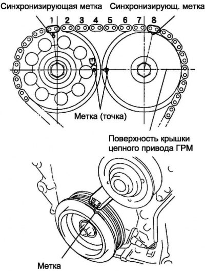
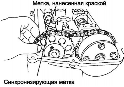
Pic. 2.175. Matching sync marks
Make sure 2 labels (points) located opposite each other. Also make sure that each of the timing marks matches the corresponding marked link of the timing chain drive, as shown in Figure 2.175. Also, make sure the timing mark on the crankshaft pulley is aligned with the timing mark «0» on the timing chain cover.
Install the chain tensioner.
Make sure the O-ring is free of dirt, then install the hook.
Apply a thin layer of engine oil to the O-ring.
Secure the chain tensioner with 2 nuts. Tightening torque: 9.0 Nm.
Note. Be careful not to crush the O-ring.
Note. If, when installing the chain tensioner, the hook disengages and releases the plunger, re-secure the plunger with the hook.
Turn the crankshaft counterclockwise, then remove the hook from the lock pin and release the plunger.
Turn the crankshaft clockwise and check that the plunger presses on the chain tensioner shoe.
If the plunger does not extend, use a screwdriver to push the shoe towards the tensioner so that the hook disengages from the stop pin and the plunger can extend.
Check and adjust valve clearance.
Install the cylinder head cover.
Install the remaining components in the reverse order of removal.