
Removal and installation
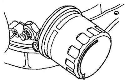
1. Unscrew the oil filter.
2. Remove the oil pan (see section "oil pan").
A) Turn away bolts and nuts of fastening of the pallet.
- Tightening torque - 9 Nm
b) Insert the blade of the special tool between the oil pan and the cylinder block and, cutting off the sealant, remove the pan.
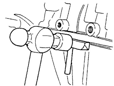
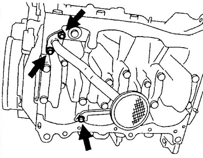
2. Remove the oil receiver by unscrewing the 2 nuts and mounting bolt.
- Tightening torque - 18 Nm
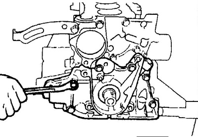
3. Remove the oil pump.
A) Turn away bolts.
- Tightening torque - 7 Nm
b) Separate the oil pump with a screwdriver by inserting it between the pump and the main bearing cap.
V) Remove the O-ring.
4. Installation is made in an order, the return to removal.
Disassembly
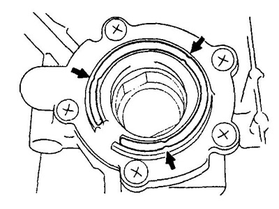
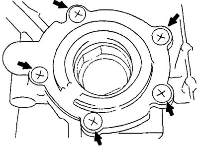
1. Loosen 5 screws and remove the housing cover.
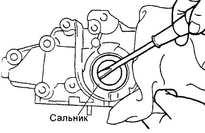
2. Remove the oil pump seal.
3. Remove the male and female rotors.
4. Remove the relief valve by removing the cotter pin, spring seat and spring.
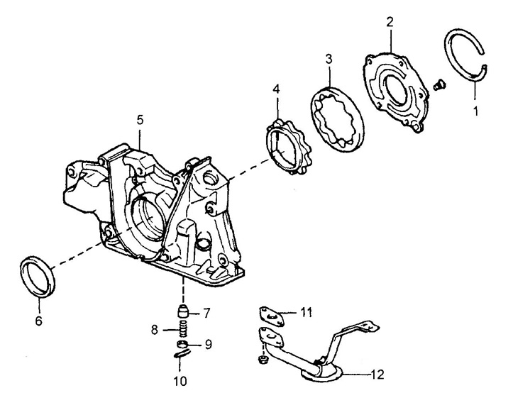
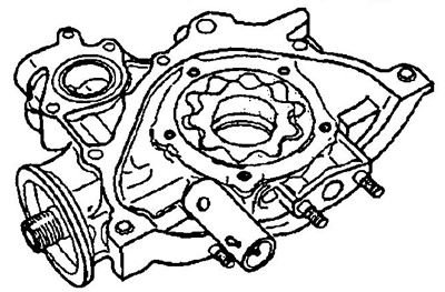
Disassembly and assembly of the oil pump (EJ-series).
1 - ring seal,
2 - oil pump cover,
3 - driven rotor,
4 - leading rotor,
5 - oil pump housing,
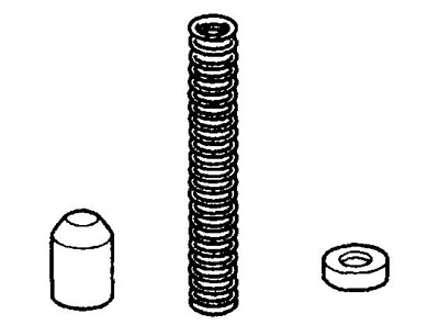
6 - stuffing box,
7 - pressure reducing valve,
8 - pressure reducing valve spring,
9 - spring seat,
10 - cotter pin,
11 - gasket,
12 - oil receiver.
Examination
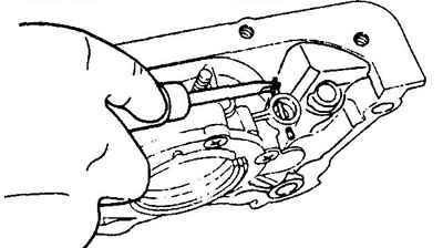
1. Check pressure reducing valve.
After lubricating the surface of the valve with fresh engine oil, install it in the mounting hole and make sure that the valve drops under its own weight.
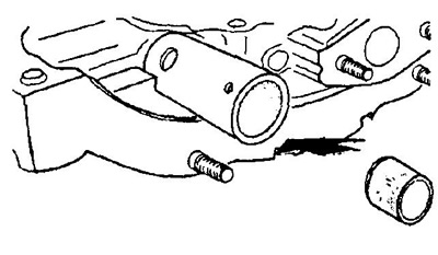
If it doesn't, replace the valve or the entire oil pump.
2. Lubricate the male and female rotors with engine oil, install them in the pump housing and check that the rotors rotate smoothly.
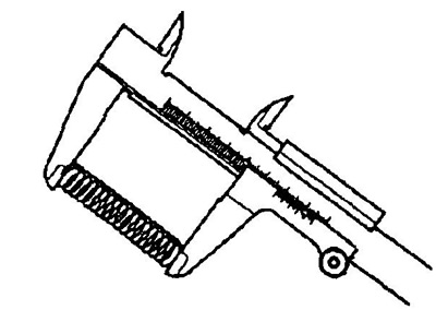
3. Measure the length of the spring.
- Nominal length - 57 mm
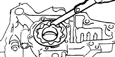
4. Using a feeler gauge, measure the radial clearance between the male and female rotor lugs.
- Nominal clearance - 0.16 - 0.24 mm
5. Using a feeler gauge, measure the radial clearance between the driven rotor and the pump housing.
- Nominal clearance - 0.20 - 0.28 mm
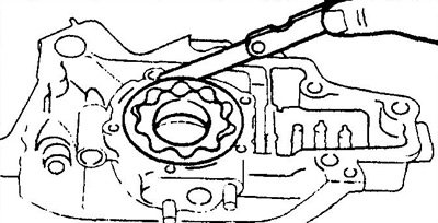
If either gap is greater than maximum, replace both rotors. Replace the entire pump if necessary.
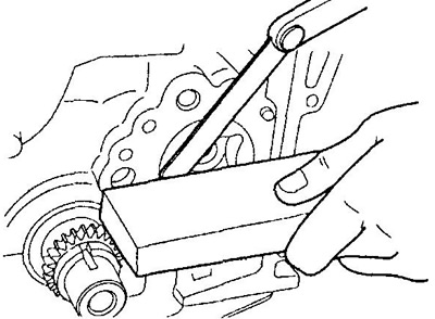
6. Using a precision ruler and feeler gauge, measure the end clearance between the rotors and the housing wall.
- Nominal clearance - 0.04 - 0.08 mm
- Maximum clearance - 0.30 mm
Assembly
1. Install pressure reducing valve, spring and spring seat, securing with cotter pin.
2. Install the oil pump seal.
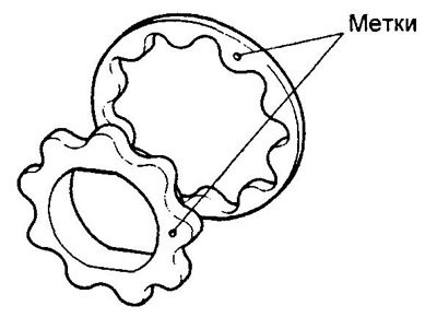
3. Install the male and female rotors.
A) Position the male and female rotors with the marks towards the housing cover as shown.
b) Install the pump housing cover and secure it with 5 screws.
- Tightening torque - 19 Nm