



Contents: Disassembling the carburetor cover…↓ Disassembling the carburetor body ↓ Carburetor Cleaning Technology ↓
It is recommended to follow some rules when performing assembly and disassembly work:
a) To make assembly easier, arrange the parts in a certain order;
b) do not confuse or lose small parts (clamps, springs, etc.);
c) use a set of specialized tools for carburetors.
Disassembling the carburetor cover (float chamber covers)
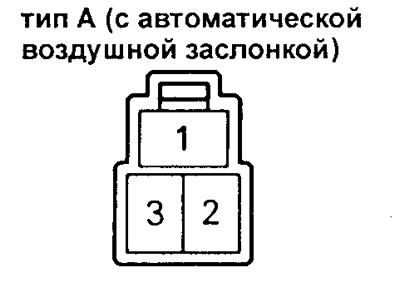
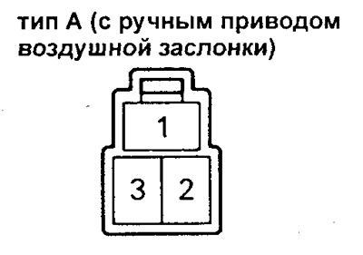
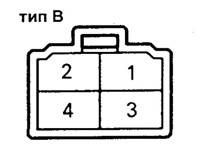
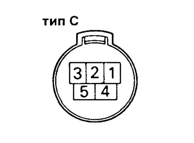
1. Disconnect the wires from the electrical connector as shown in Figures 1, 2, 3, 4.
 |  |
 |  |
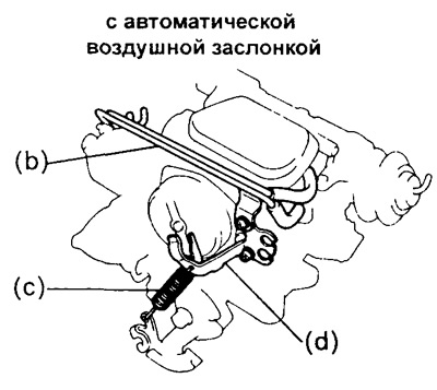
2. Remove the following parts:
a) vacuum hoses;
b) a vacuum tube with vacuum hoses;
c) accelerator return spring;
g) (Carburetor with automatic choke)
air damper spring bracket.
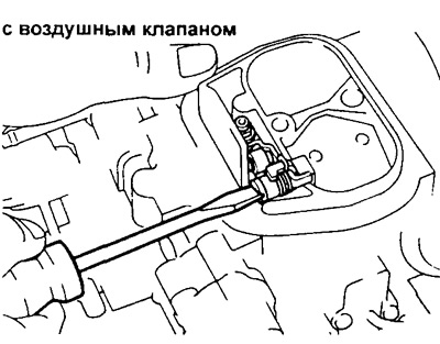
3. (carburetor with an additional damper in the secondary chamber) Remove the metering needle by unscrewing the screw and removing the flat washer.
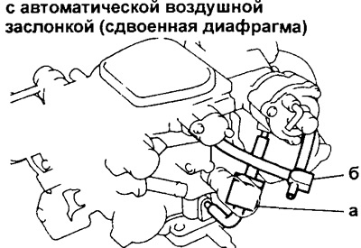
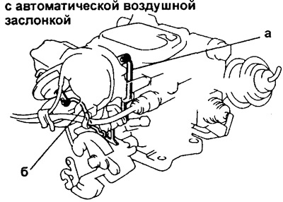
4. Remove the vacuum hoses of the air damper switch (CB) and the cam of the idle Speed Increase System (FICB) switch.
a) Remove the vacuum hoses and the pneumatic flow valve (vTV pneumatic diode) from the air damper position switch (ADS).
b) (Option with cam switch of the idling speed control system (FICB))
(The article is taken from a web resource: ToyotaMAN)
Remove the vacuum hoses and FICB assembly.
5. Remove the carburetor cover (float chamber cover).
a) (carburetor without additional valve in the secondary chamber and with increased idle speed control cam (FICB))
Disconnect the thrust of the cam switch of the idling Speed Increase System (FICB).
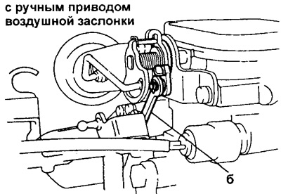
b) Disconnect the idle speed increase mechanism rod.
 |  |
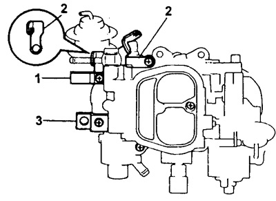
c) After unscrewing the five screws securing the carburetor cover, remove the plate with the carburetor number (1), bracket A (2) and bracket B (3).
d) Remove the float chamber cover together with the gasket.
6. Remove the float together with the fuel supply needle valve, having first removed the float axis. Remove the gasket from the float chamber cover.
7. Remove the valve seat and seat gasket.
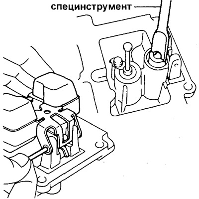
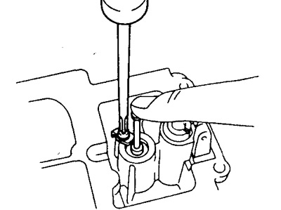
8. Remove the economizer drive piston:
a) loosen the screw securing the retainer (holder);
b) holding the piston, unscrew the screw and remove the retainer;
c) then remove the piston and spring.
9. (Carburetor with float chamber unbalance system (OVCV))
Remove three screws and remove the overhead cam control valve (OVCV) housing.
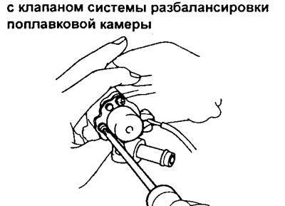
10. (Carburetor with automatic choke)
Remove the spring housing by unscrewing the three screws and removing the retainer and gasket.
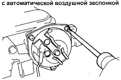
11. Remove the air damper switch (ADS).
(Carburetor with automatic choke (variant with a double diaphragm in its drive)).
a) Unscrew the three screws, remove the cover, diaphragm, housing and spring.
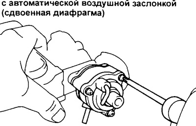
b) Remove the split ring, cuff and diaphragm.
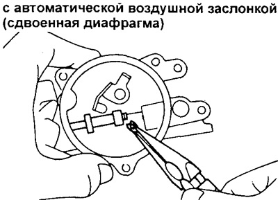
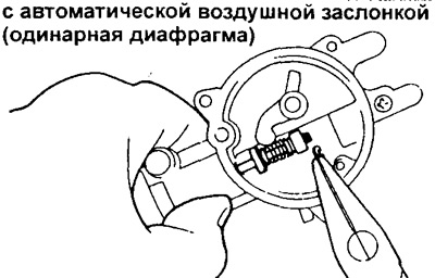
(Carburetor with automatic choke (variant with a single diaphragm in its drive))
a) Unscrew the three screws, remove the cover and spring.
b) Remove the split ring, limiter, spring, cuff and diaphragm.
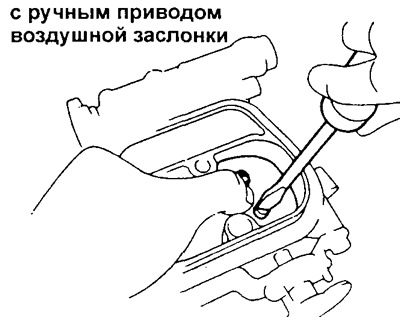
(Carburetor with manual choke)
a) File down the riveted ends of the air damper mounting screws.
b) Loosen the two screws securing the air damper plate and remove it.
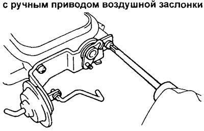
c) Remove the air damper shaft and spring.
d) Unscrew the two screws, remove the bracket and the air damper switch (ADS) housing.
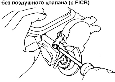
14. (Carburetor without additional throttle in the secondary chamber and with a high idle speed control cam (FICB) switch)
Remove the cam switch of the Idle Speed Control System (FICB).
Disassembling the carburetor body
1. Remove the throttle actuator or throttle linkage (TR).
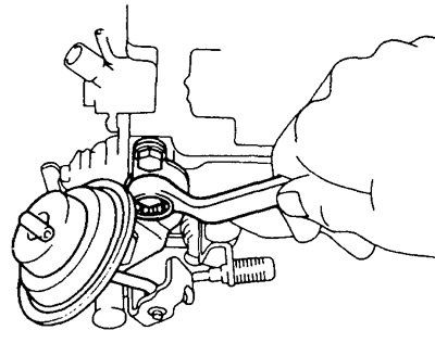
2. Unscrew the jets and economizer:
a) idle jet;
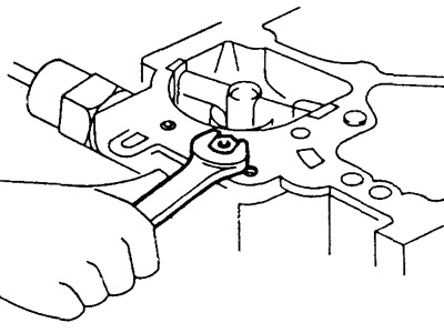
b) economizer jet;
c) (Carburetor with an additional damper ("air valve") in the secondary chamber) the guide of the metering needle;
d) secondary chamber main fuel jet;
d) plug and gasket;
e) the main fuel jet of the primary chamber and the gasket.
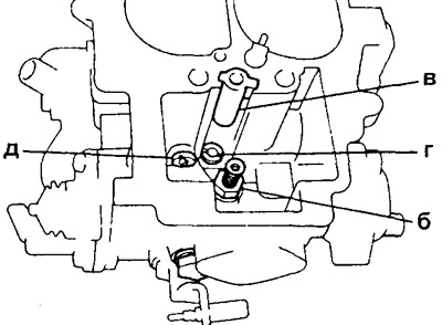
3. (option without additional damper in the secondary chamber) Remove the two screws, small diffuser and gasket.
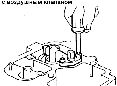
4. Unscrew the solenoid valve (or valves) fuel supply shutdown.
5. Remove the accelerator pump by unscrewing the four screws, removing the pump body, diaphragm and spring.
6. (Carburetor with additional accelerator pump (AAP)) Remove the additional accelerator pump (AAP) by unscrewing the three screws, removing the housing, spring and diaphragm.
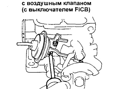
7. (Carburetor with additional flap in secondary chamber and high idle speed control cam (FICB)) Disconnect the thrust of the cam switch of the idling Speed Increase System (FICB). Remove the high idle speed control cam position switch by removing the two screws, disconnecting the rod, and removing the FICB switch housing.
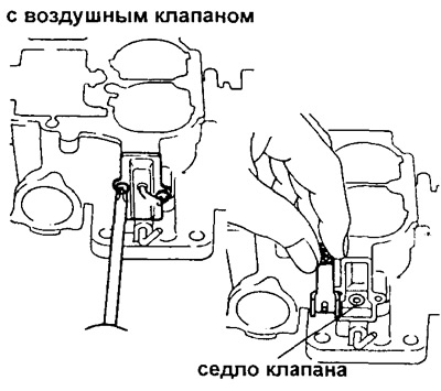
8. (Carburetor with an additional damper in the secondary chamber) Remove the hot idle mixture corrector (HIC) by removing the two screws, cover and gasket, HIC valve and valve seat.
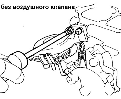
9. (option without additional damper in the secondary chamber) Remove the secondary throttle actuator:
a) remove the return spring;
b) unscrew two screws;
c) disconnect the rod and remove the housing of the secondary chamber throttle pneumatic drive.
10. (option without additional damper in the secondary chamber) Disassemble the secondary throttle actuator by removing the four screws from the actuator housing.
11. Unscrew the plug.
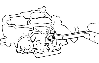
12. Remove the float chamber sight glass by unscrewing the two screws, removing the glass and the O-ring.
13. Remove the three screws and separate the carburetor body from the mixing chamber body; remove the insulator.
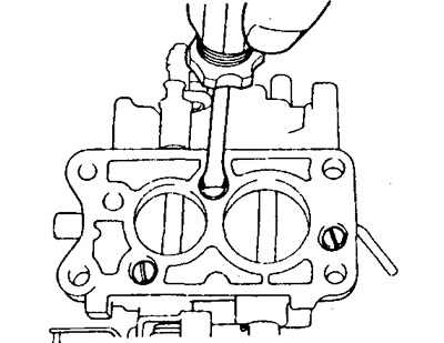
Carburetor Cleaning Technology
Clean the disassembled carburetor components before checking:
a) wash and clean the cast parts of the carburetor with a soft brush and liquid cleaner;
b) remove carbon residue from the throttle valve;
c) wash the remaining parts with liquid remover;
d) Blow out the channels and jets of the carburetor.