



Contents: Cold engine ↓ Warm engine ↓
1. Remove the air filter or air duct from the carburetor.
2. Check the carburetor and drive.
a) Check the presence and position of the adjusting screws, plugs and bolts.
b) Check the condition and wear of the drive parts, the presence of latches, etc.
c) Check that the throttle valve is fully open when the accelerator pedal is fully depressed.
3. Check the fuel level in the float chamber using the marks on the sight glass. If the fuel level is outside the required limits, adjust it.
Cold engine
4. Check the automatic air damper control system.
a) Start the engine.
b) Make sure that the air damper begins to open as the heater body warms up.
c) Turn off the engine.
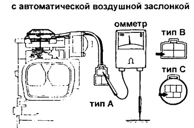
d) Disconnect the carburetor electrical connector.
d) Using an ohmmeter, measure the resistance between the carburetor connector terminal and ground, the value of which at an air temperature of 20°C is:
For engines:
- 2Y-C (U) and 3Y-C (U) - 23-25 Ohm
- for the rest of the Y series - 17-19 Ohm
5. Check the air damper position switch system (SV system).
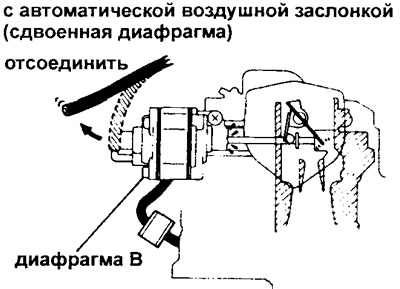
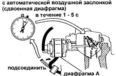
(Option with automatic air damper and double diaphragm in the pneumatic actuator of the switch)
a) Start the engine.
b) When the coolant temperature is below 5°C, disconnect the vacuum hose from diaphragm B and check that the flap does not move.
c) Connect the vacuum hose to diaphragm B.
d) Disconnect the vacuum hose from switch diaphragm A and check that the choke plate moves.
d) Connect the vacuum hose to diaphragm A and check that after connecting the hose the flap moves for the set time (1-5 s).
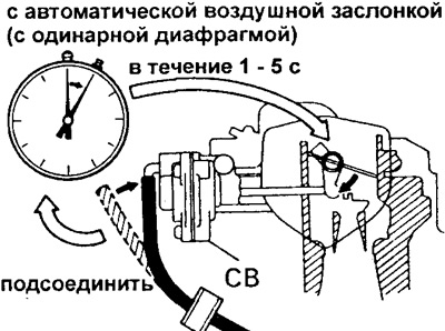
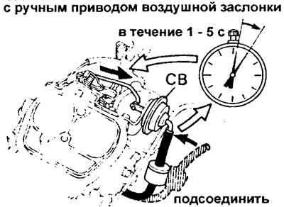
(Option with automatic air damper with single diaphragm in pneumatic drive)
a) Start the engine.
b) Disconnect the vacuum hose from the choke switch (CS) and check that the choke actuator moves.
c) Connect a vacuum hose to the diaphragm switch mechanism (DS) and check that the air damper plate moves within the specified time (1-5 sec).
 |  |
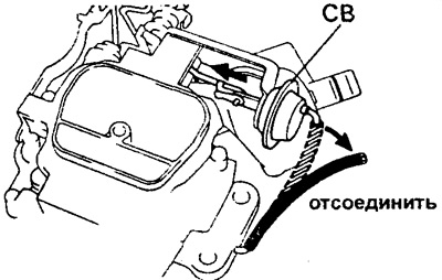
(Option with manual air damper drive and single diaphragm in the pneumatic drive of the switch)
a) Start the engine.
b) Disconnect the vacuum hose from the choke switch (CS) diaphragm mechanism and check that the choke actuator mechanism moves.
c) Reinstall the vacuum hose.
6. (If there is an automatic air damper control system (CO-systems) and the cam of the increased idle speed control mechanism (FICB))
Check the cam switch of the Extended Idle Speed Control Mechanism (FICB).
a) Disconnect the vacuum hose from the diaphragm cam drive mechanism (FICB).
b) When the coolant temperature is below 55°C°C, press and release the accelerator pedal.
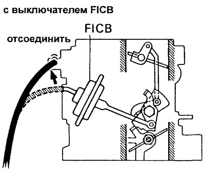
c) Start the engine.
d) Connect the vacuum hose and make sure the choke actuator does not move.
7. (If there is an additional accelerator pump (AAP) system)
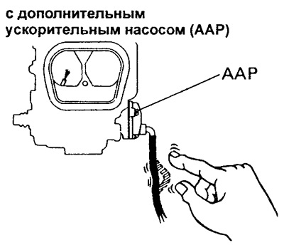
Check the auxiliary accelerator pump (AAP) system.
a) Make sure the coolant temperature is below 55°C and start the engine.
b) Clamp the AAR hose and turn off the engine.
c) Release the hose and make sure that fuel is injected from the AAP injector.
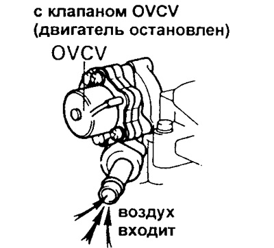
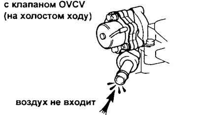
8. (If there is a float chamber imbalance valve (oVCV carburetor ventilation systems)) Check the operation of the imbalance system valve (ventilation systems) float chamber.
a) Disconnect the ventilation hose from the carburetor.
b) Apply air to the vent tube and make sure the OVCV valve is open.
c) Start the engine. With the engine idling, apply air to the vent tube and make sure the OVCV valve is closed.
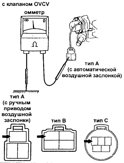
d) Disconnect the electrical connector from the carburetor.
d) Using an ohmmeter, measure the resistance between the OVCV terminal on the connector and ground.
- Resistance value (cold engine): 63-73 Ohm.
e) Reconnect the ventilation hose.
Warm engine
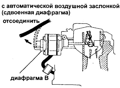
9. (Option with automatic air damper with double diaphragm in pneumatic drive of air damper position switch)
Check the operation of the air damper (AD) position control ("switch") system.
a) After the engine has warmed up, disconnect the vacuum hose from diaphragm B and check that the throttle plate moves.
b) Connect the vacuum hose to diaphragm B.
10. (If there is an automatic air damper control system (CO-systems) and the cam of the increased idle speed control mechanism (FICB))
Check the cam switch of the Extended Idle Speed Control Mechanism (FICB).
a) Warm up the engine to normal operating temperature and turn it off.
b) Disconnect the vacuum hose from the diaphragm mechanism of the air damper actuator (and FICB cam).
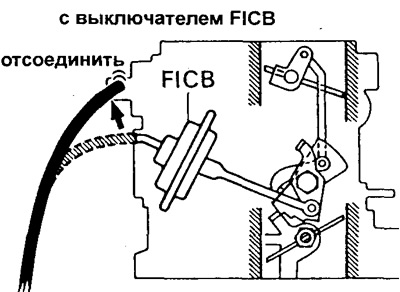
c) Install the high idle speed cam (FICB). To do this, while holding the throttle slightly open (1), close the air flap (2) and hold it in the closed position as the throttle (3) is released.
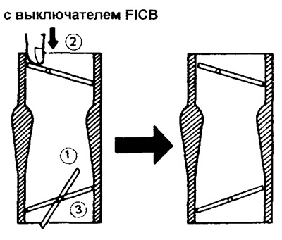
d) Start the engine without touching the accelerator pedal.
d) Connect the vacuum hose and check that the choke actuator moves and the FICB cam moves to position 3.
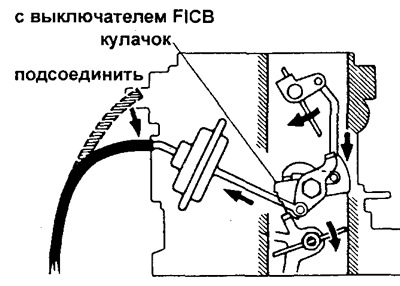
11. (Option with automatic air damper)
Check the full opening of the choke by making sure the choke plate opens fully.
12. (If there is an additional accelerator pump (AAP) system)
Check the auxiliary accelerator pump (AAP) system.
a) Warm up the engine to normal operating temperature.
b) With the engine running, clamp the AAP hose, then turn off the engine.
c) Release the AAP hose and make sure that fuel is not injected from the AAP nozzle.
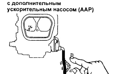
13. (If there is an additional accelerator pump (AAP) system)
Check the auxiliary accelerator pump (AAP) diaphragm.
a) Start the engine. With the engine running, disconnect the hose from the AAP diaphragm mechanism.
b) With the engine idling, apply vacuum directly to the AAP diaphragm and then remove the vacuum.
c) Make sure that the engine speed changes when the vacuum is removed.
d) Reconnect the hose to the AAP diaphragm mechanism.
If a malfunction occurs, replace the AAP diaphragm.
14. Check the accelerator pump (main).
Open the throttle and make sure that fuel is injected through the injector.
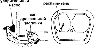
15 Install the air filter or air duct onto the carburetor.
16*. Check for increased idle speed when the engine warms up.
17* Check the normal idle speed and mixture composition.
18*. Check the rotation speed set by the throttle valve opening mechanism.
19*. Check the rotation speed set by the manipulator (positioner) throttle valve.
20*. Check the increase in idle speed set by the amplifier in the control system.
* See pp. 8-10.