
Second modification (without additional damper) has an automatic pneumatic actuator of the throttle valve of the secondary chamber, and the air path of each chamber is made according to a three-diffuser scheme.
Carburetor - two-chamber with sequential mechanical opening of the throttle valve of the secondary chamber (see fig. "Carburetor diagram" on page 32).
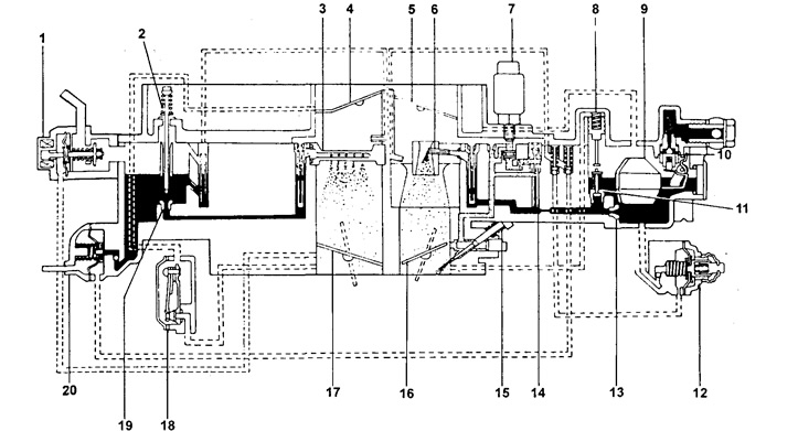
1 - valve of the unbalance system of the float chamber (OVCV),
2 - dosing needle,
3 - main atomizer of the secondary chamber,
4 - additional shutter of the secondary chamber,
5 - air damper of the primary chamber,
6 - main atomizer of the primary chamber,
7 - solenoid valve for cutting off the fuel supply of the primary chamber,
8 - economizer drive piston,
9 - float,
10 - needle valve,
11 - economizer valve,
12 - accelerator pump,
13 - main fuel jet of the primary chamber,
14 - idle fuel jet,
15 - adjusting screw for the composition of the mixture for normal idling,
16 - throttle valve of the primary chamber,
17 - throttle valve of the secondary chamber,
18 - idle mixture composition corrector when the engine warms up,
19 - main fuel jet of the secondary chamber,
20 - additional accelerator pump (AAR).
The float chamber is located in the carburetor body and has a float 9 and a needle valve 10, which has a spring and a support ball inside to dampen the float vibrations. Unbalance valve 1 is installed in the float chamber (carburetor ventilation valve).
The air path of the primary chamber includes: an air damper 5, a large diffuser, a small diffuser with a spray 6, a primary throttle damper 16.
The composition of the main metering system of the primary chamber includes: the main fuel jet 13, the main air jet and the atomizer 6. Fuel enters the same fuel path through the valve 11 of the economizer 8 with a pneumatic drive.
The idling system of the primary chamber of the carburetor, included in the main metering system after the main fuel jet, has: an idle fuel jet 14, an idle air jet, a solenoid valve 7 for turning off the fuel supply, an idle mixture adjustment screw 15 and two outlets, through which fuel enters the mixing chamber of the carburetor. Solenoid valve 7 turns off the fuel supply in forced idle modes, and also shuts off the fuel path after the engine is stopped.
The accelerator pump 12 of the diaphragm type, when the throttle is quickly opened, supplies fuel to the primary chamber of the carburetor in the annular gap between the large and small diffusers.
The carburetor has an auxiliary accelerator pump 20 with a pneumatic drive. It functions only when the engine is cold and supplies fuel to the same place as the main accelerator pump 12.
There is virtually no diffuser in the air path of the secondary chamber. Its role is performed by an additional damper 4 ("air valve"), eccentrically mounted on the axis at the entrance to the secondary air path. This damper is acted upon by the moment of forces created by the pressure difference on both sides of it and the pressure of the air velocity head. At a low engine speed, this damper remains closed regardless of the position of the secondary throttle valve 17, which has a direct kinematic connection with the primary throttle valve 16. The presence of an additional damper 4 prevents a sharp lean mixture when the throttle valves 16 and 17 are quickly and fully opened.
The main dosing system of the secondary chamber includes: the main fuel jet 19, the dosing needle 2, kinematically connected with the additional damper 4, the air jet and the atomizer 3. The opening of the additional damper 4 is accompanied by an increase in the flow area of the main fuel jet 19, which provides the required composition of the mixture.
The secondary chamber also has an econostat, which, at high speeds, supplies fuel to the air path above the atomizer 3.
The corrector for the composition of the idle mixture of the warmed-up engine 18 is also included in the secondary chamber. When the engine warms up, the corrector provides air from the inlet pipe of the secondary chamber directly to the throttle space, which leads to the necessary depletion of the mixture.
Structurally, the carburetor consists of three main assembly units (see fig. "Carburetor parts" on page 33): carburetor cover assembly 6, carburetor body 11 assembly and mixing chamber body 21 assembly. An insulator 13 is installed between the last two nodes.
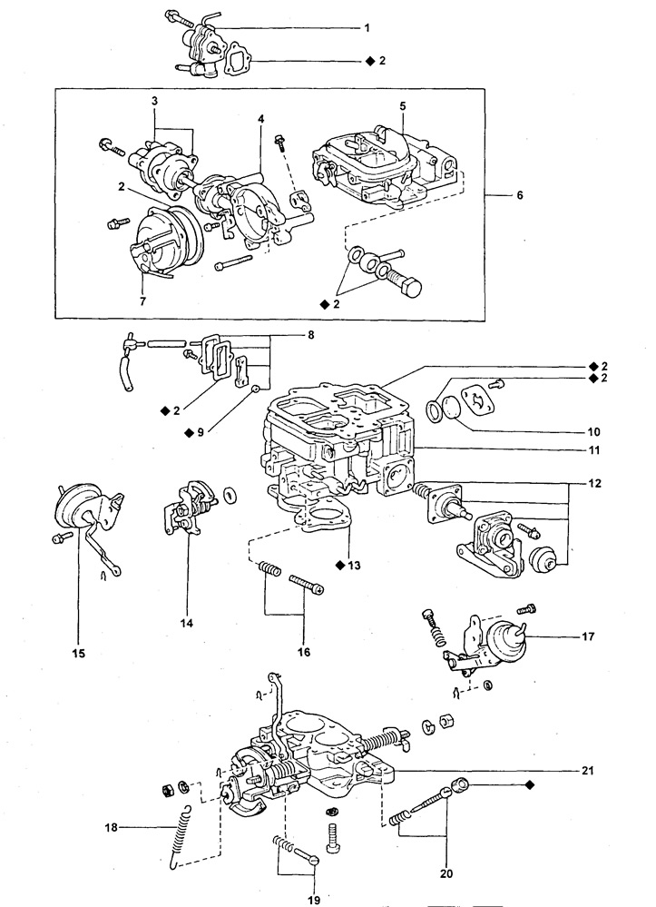
1 - carburetor ventilation valve (system valve "imbalances" float chamber (OVCV)),
2 - gasket,
3 - position regulator ("switch") damper position (SW),
4 - thermostat housing,
5 - carburetor cover (float chamber cover),
6 - carburetor cover (float chamber cover) assembled,
7 - spring housing (air damper coil heater),
8 - idling mixture composition corrector when the engine warms up,
9 - valve seat,
10 - sight glass,
11 - carburetor body,
12 - accelerator pump,
13 - insulating gasket,
14 - cam of the idle speed increase system,
15 - cam switch for the idle speed increase system,
16 - idle speed adjusting screw,
17 - opening mechanism or manipulator (positioner) throttle,
18 - accelerator return spring,
19 - adjusting screw for increased idle speed when the engine is warming up,
20 - adjusting screw for the composition of the mixture for normal idling,
21 - body of the mixing chambers of the carburetor ("carburetor flange"),
♦ - a part that cannot be reused.
Installed in the carburetor cap (see "Carburetor parts" us. 33): air damper with automatic control system ("switch" damper position (SW) 3, air damper coil heater 7, thermostat 4), float chamber ventilation valve 1 (OVCV), needle valve, float and fuel inlet.
The carburetor body assembly houses (see fig. "Carburetor parts" on page 33): diffusers, fuel and air jets, sight glass 10 of the float chamber, corrector 8 of the composition of the idling mixture of a warm engine, cam 14 for setting an increased idle speed and "switch" 15 positions of this cam, position controller (manipulator) throttle valve 17, pneumatically controlled economizer, accelerator pump 12, auxiliary accelerator pump (see pos. 9 in fig. page 34), fuel shutoff solenoid valve (see 8 in fig. page 34).
The mixing chamber assembly includes (see fig. "Carburetor parts" on page 33): primary and secondary throttle valves, their drive, normal idle mixture adjustment screw 20, idle mixture adjustment screw at high speed 19.