



Note: Use only new gaskets and O-rings during assembly.
Assembling the carburetor body
1. Assemble the carburetor body with the mixing chamber body (the lower part or "flange" of the carburetor), installing a new insulator and securing the connected body parts with three screws.
2. Install the sight glass onto the new O-ring and secure it with two screws.
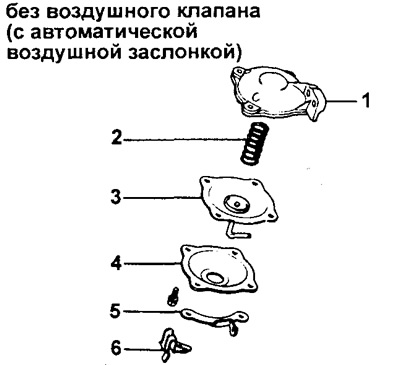
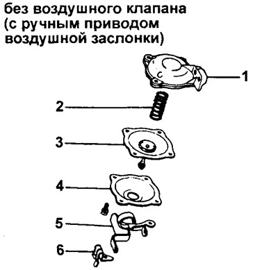
3. (variant with a carburetor without an additional damper in the secondary chamber)
Assemble the secondary throttle actuator by installing the following parts in the order shown in the figures: (1) housing, (2) spring, (3) diaphragm, (4) cover, (5) retainer, (6) cable clamp.
 |  |
4. (option without additional damper in the secondary chamber) Install the secondary throttle valve actuator.
a) Install the sealing ring.
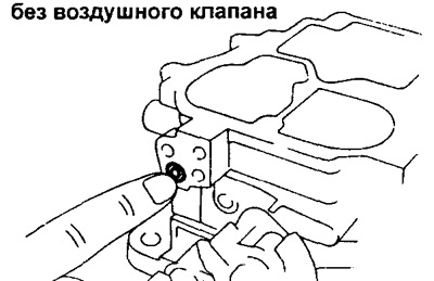
b) Secure the drive rod and attach the drive housing to the carburetor housing with two screws.
c) Install the return spring.
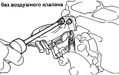
5. (a variant of a carburetor with an additional damper in the secondary chamber)
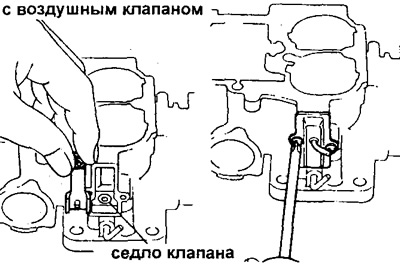
Install the Hot Idle Compensator (HIC) by installing the valve seat and HIC valve and securing the HIC body with two screws.
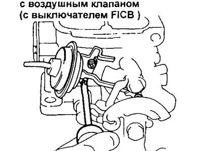
6. (carburetor version with additional air damper in the secondary chamber and with cam switch of the idle speed increase system (FICB)) Connect the rod and secure the cam switch (FICB) with two screws.
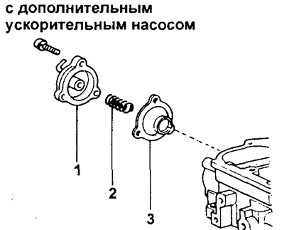
7. (Carburetors with auxiliary accelerator pump (AAP)) Install the diaphragm (1), spring (2) and cover (3) of the auxiliary accelerator pump (AAP) and secure them with three screws.
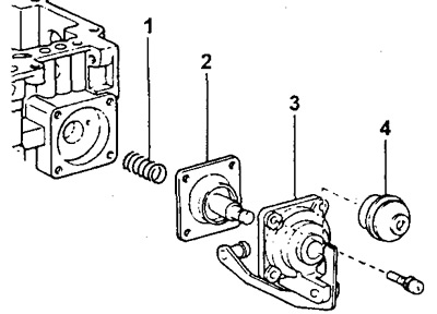
8. Install the accelerator pump by securing the spring (1), diaphragm (2), cover (3) and guide (4) with four screws (if there is one).
9. Install the solenoid valve (or valves) shutting off the fuel supply using a new gasket and a new O-ring.
10. (option without additional damper in the secondary chamber) Install the small secondary chamber diffuser using two screws along with a new gasket.
11. Install the jets and economizer valve, observing the sequence shown in the figure:
a) Primary chamber main fuel jet with new gasket;
b) Channel plug with a new gasket;
c) Main fuel jet of the secondary chamber;
g) (Only for carburetor with additional damper in secondary chamber) dosing needle guide;
d) Economizer valve;
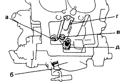
e) Idle jet with new O-ring seal.
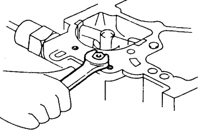
12. Install the throttle opening mechanism or throttle control (TC) mechanism.
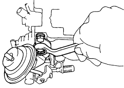
Assembling the carburetor cover (float chamber covers)
1. (Carburetor version without additional choke in the secondary chamber and with increased idle speed control cam (FICB) switch) Install the increased idle speed control cam (FICB) switch.
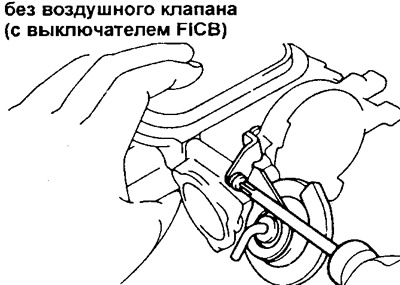
2. Set the air damper (AD) position control ("switch").
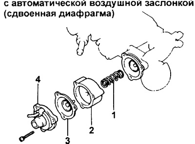
(Carburetor with automatic choke (variant with a double diaphragm in the mechanism of its pneumatic drive))
a) Insert the inner diaphragm into the thermostat housing, install the cuff and split retaining ring.
b) Insert the inner diaphragm stem into the hole in the thermostat housing.
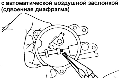
c) Connect with three screws: spring (1), body (2), outer diaphragm (3) and cover (4).
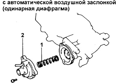
(Carburetor with automatic choke (variant with a single diaphragm in the mechanism of its pneumatic drive))
a) Insert the diaphragm into the thermostat housing, install the cuff, spring, and retainer with a split retaining ring.
b) Insert the diaphragm stem into the hole in the thermostat housing.
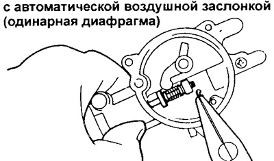
c) Fasten the spring (1) and cover (2) with three screws.
(Carburetor with manual choke)
a) Secure the air damper switch (ADS) with two screws.
b) Install the air damper shaft together with the spring.
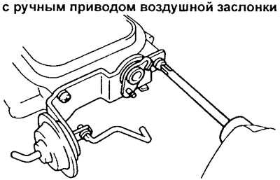 | 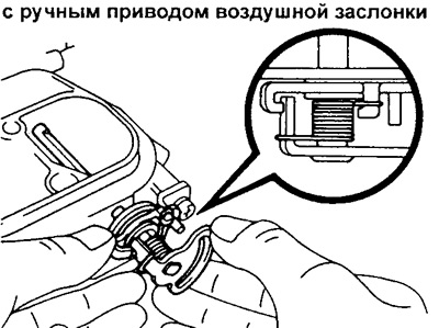 |
c) Secure the air damper plate with two screws (apply sealant to the threads of the mounting screws first).
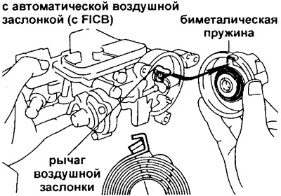
3. (Carburetor with automatic choke)
Install the spring housing.
a) Install the gasket and thermostat housing.
b) (Carburetor with Fast Idle Control Cam (FICB) switch)
Align the bimetallic spring with the choke lever and install the spring housing.
(Carburetor without cam switch of idling Speed Increase system (FICB)) Align the bimetallic spring with the wire loop and install the spring housing by aligning it with the air damper lever as shown in the figure.
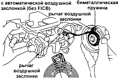
c) Align the center line of the thermostat housing with the line on the spring housing and secure the housing with three screws.
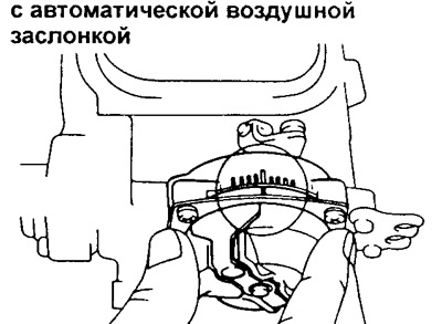
d) Check the operation of the air damper.
4. (Carburetor with float chamber unbalance system valve (oVCV valve))
Install a new gasket and secure the OVCV valve with three screws.
5. Install the economizer piston together with the spring and retainer, securing the retainer with a screw.
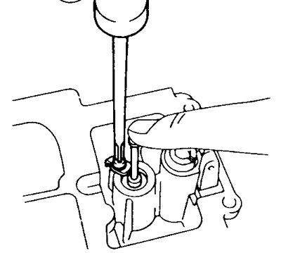
6. Install the new gasket and needle valve seat into the carburetor cover intake hole.
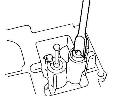
7. Install the needle valve and float.
Hook the needle valve wire clamp (loop) to the float adjustment plate. Then install the float and fix it on the axle.
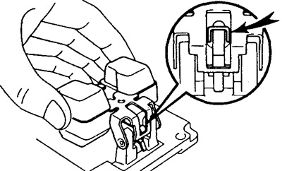
8. Adjust the float level.
Note: Measurements must be taken without the gasket on the carburetor cover.
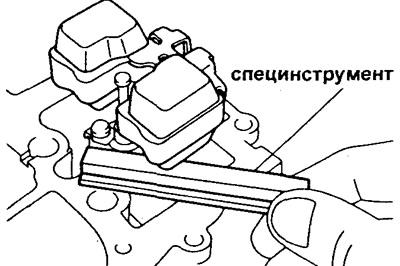
a) With the cover installed with the float facing up, measure the gap between the top point of the float and the plane of the cover joint.
- Float level (raised position) — 8.2 mm
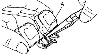
b) If necessary, adjust the level by bending the float adjustment bar (A).
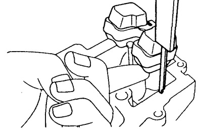
c) Raise the float and, using a caliper with a depth gauge, check the distance between the surface of the cover joint and the bottom of the float.
- Float level (lower position) — 47.1 mm
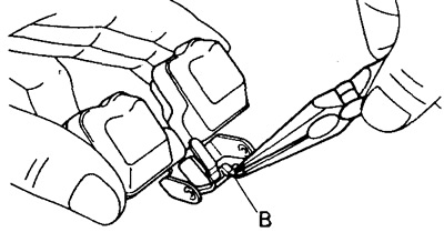
d) If necessary, adjust by bending the float plate marked with the symbol (B).
9. Install the carburetor cover (float chamber cover).
a) Install a new gasket; install the carburetor cover assembly onto the carburetor body.
b) Secure the following parts with five screws: brackets A (1) and B (2), and the number plate (3).
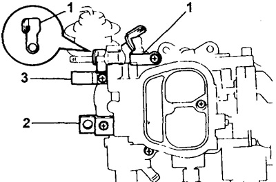
c) Connect the idle speed increase system rod (4).
d) (Carburetor without additional throttle in the secondary chamber and with increased idle speed control switch (FICB))
Attach the thrust of the high idle Speed control cam switch (FICB) (5).
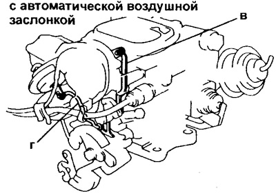 | 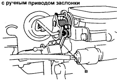 |
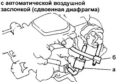
10. Install the choke switch (CH) and idle speed control cam (FICB) switch vacuum pipes.
a) Install vacuum tubes and pneumatic diode (vTV straight-through pneumatic valve) (1) Air damper position switch (ADS).
b) (Carburetor with Fast Idle Control Cam (FICB) switch)
Install the vacuum tubes and fitting (2) of the cam switch (FICB).
11. (carburetor with an additional damper in the secondary chamber) Install the metering needle by inserting it into the guide in the carburetor cover and fitting the spring.
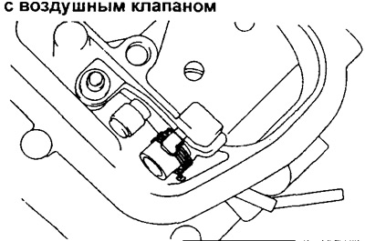
Then install the flat washer and tighten the clamping screw.
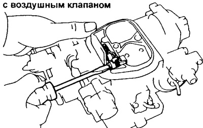
12. Install the following parts:
a) (For carburetor with automatic choke) spring bracket;
b) (For 2Y-C(U) and 3Y-C(U) engines) vacuum tubes and vacuum hoses;
c) accelerator return spring;
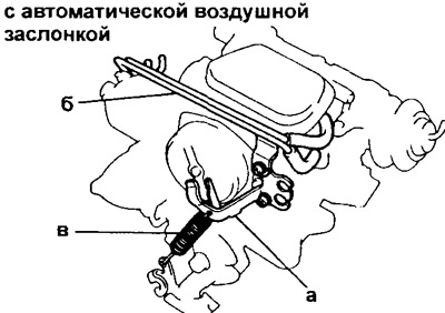
g) (For engines with vacuum hoses)
Vacuum hoses according to the labels installed during disassembly.
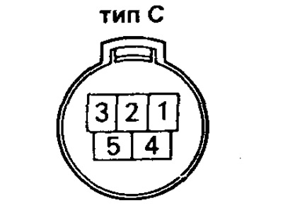
13. Connect the wires to the connectors:
a) (For engines with automatic choke) Spring housing wire;
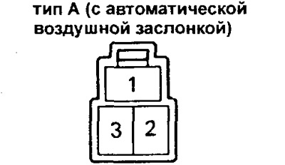
b) (For engines with float chamber unbalance valve (oVCV valve)) OVCV imbalance valve wire;
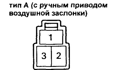
v) (For engines with fuel shut-off solenoid valve)
solenoid valve wire (electromagnetic valves).
 |  |
14. Check each moving part of the carburetor for smooth movement/operation.