



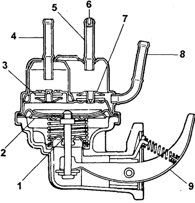
Pump diagram:
1 - sealing cuff,
2 - diaphragm,
3 - inlet valve,
4 - inlet pipe,
5 - fuel return pipe,
6 - fuel return tube jet,
7 - graduation (injection) valve,
8 - outlet pipe,
9 - pump lever.
Removal the fuel pump
1. Disconnect the fuel hoses from the pump.
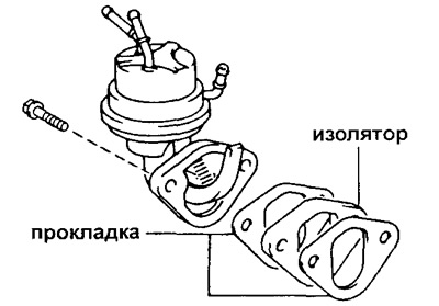
2. Remove the pump together with the gasket or insulator by unscrewing the two bolts.
Checking the pump (leak test)
Before performing the main check of the pump, perform the following operations:
- a) Run some fuel through the pump to ensure that the pump valves are operating properly (dry valves cannot work properly);
- b) Without blocking the pump tubes, operate the pump lever to assess the amount of force applied and the play on the lever; the same force should be applied when checking the pump.
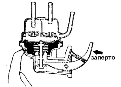
1. Check the inlet valve. Cover the outlet pipe and the fuel return pipe with your finger and press the pump lever once or twice; make sure that the free play of the lever has increased and that there is no force on the lever.
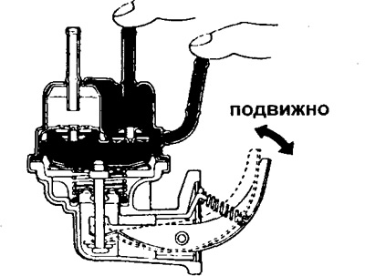
2. Check the release valve.
Place your finger over the inlet tube and make sure the lever is locked (the force required to move the lever has increased compared to that which occurred during preliminary tests).
Attention:
- Never apply more force on the lever than was applied during the preliminary check of the pump.
- This also applies to points 3 and 4.
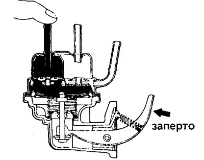
3. Check the diaphragm.
Close the inlet, outlet and return pipes with your finger and make sure the pump is blocked. Caution: If the results of the previous checks do not meet the requirements of the specifications, the pump is not sealed.
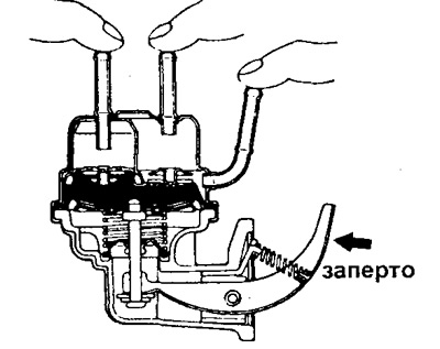
4. Check the sealing cuff. Close the vent and make sure the pump is blocked.
Installing a fuel pump
1. Install the pump, first installing new gaskets and an insulator; secure the pump with two bolts.
- Tightening torque - 18 Nm
2. Connect the fuel hoses to the pump.
3. Start the engine and check for leaks.