
1) The air paths of the primary and secondary chambers are made according to the so-called three-diffuser scheme: a large diffuser and a double small diffuser with a spray.
2) There is no additional air damper in the secondary chamber ("air valve").
3) The throttle valve of the secondary chamber is driven by a diaphragm mechanism.
4) In the fuel path of the transitional system of the secondary chamber, its own solenoid valve 2 for turning off the fuel supply is installed.
Carburetor - two-chamber with sequential opening of the throttle valves of the primary and secondary chambers (see "Carburetor diagram").
A float 8 and a needle valve 9 are placed in the float chamber of the carburetor. To dampen the vibrations of the float, the needle valve has a spring and a support ball inside.
The air path of the primary chamber includes: an air damper 4, a small double diffuser with a spray 5, a large diffuser and a throttle damper 15.
The main metering system of the primary chamber includes the main fuel jet 11, the main air jet and the atomizer 5. Fuel enters the same fuel path through the economizer 10.
The idle system of the primary chamber is included in the main metering system after the main fuel jet 11 and includes: an idle fuel jet 13, an idle air jet, a solenoid valve for shutting off the fuel supply 6, an idle mixture adjustment screw 14 and two output holes through which fuel enters the mixing chamber of the carburetor. Solenoid valve 6 turns off the fuel supply through the idle system in forced idle modes, and also shuts off the fuel path after the engine is stopped.
The accelerating pump 12 of the diaphragm type with a mechanical drive, when the throttle valve of the primary chamber is quickly moved, supplies fuel through the discharge valve into the primary chamber into the annular gap between the large and small diffusers.
The carburetor has an auxiliary accelerator pump 20 with a pneumatic drive. It functions only when the engine is cold and supplies fuel to the same place as the main accelerator pump 12.
The air path of the secondary chamber includes: a double small diffuser with atomizer 3, a large diffuser and a secondary throttle valve 16. The latter is controlled by a diaphragm mechanism 17 depending on the ratio of vacuums in the large diffusers of the primary and secondary chambers of the carburetor. The opening of the throttle valve 16 is possible only after the engine has warmed up, and also after the throttle valve 15 of the primary chamber has been opened to a certain angle.
The main dosing system of the secondary chamber includes: the main fuel jet 19, the main air jet and the atomizer 3.
The secondary chamber also has an econostat, which, at high speeds, supplies fuel to the annular gap between the large and small diffusers. The transition system of the secondary chamber, included after the main dosing system, has a jet at the outlet to the air path of the secondary chamber. When the secondary throttle is fully closed, this channel is above it - in the zone of high pressure, and no fuel flows through it. But with a slight opening of the throttle valve of the secondary chamber, the output of the transitional system is in the zone of increased vacuum, and fuel begins to flow through it into the air path, preventing the mixture from depleting. The fuel path of the transition system includes a solenoid valve for shutting off the fuel supply 2, which performs the same functions as a similar valve in the idle system of the primary chamber.
The corrector of the composition of the mixture of the warmed-up engine 18 is also included in the secondary chamber. When the engine is warmed up, the corrector provides air supply from the inter-diffuser space of the secondary chamber directly to the throttle space, which leads to depletion of the mixture.
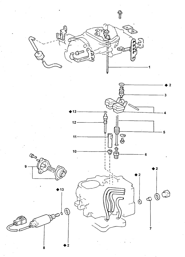
1 - dosing needle,
2 - gasket,
3 - needle valve,
4 - float,
5 - economizer drive piston,
6 - economizer valve,
7 - main fuel jet of the primary chamber,
8 - solenoid valve for cutting off the fuel supply of the primary chamber,
9 - optional (auxiliary) accelerator pump (AAR),
10 - main fuel jet of the secondary chamber,
11 - dosing needle guide,
12 - idle jet,
13 - annular sealing gasket,
♦ - a part that cannot be reused.
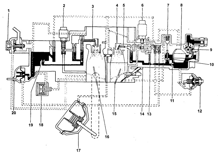
1 - carburetor ventilation valve (system valve "imbalances" float chamber (OVCV)),
2 - fuel cutoff solenoid valve,
3 - atomizer of the secondary chamber,
4 - air damper,
5 - atomizer of the primary chamber,
6 - solenoid valve for cutting off the fuel supply of the primary chamber,
7 - economizer drive piston,
8 - float,
9 - needle valve,
10 - economizer valve,
11 - main fuel jet of the primary chamber,
12 - accelerator pump,
13 - idle fuel jet,
14 - screw for adjusting the composition of the mixture at idle,
15 - throttle valve of the primary chamber,
16 - throttle valve of the secondary chamber,
17 - pneumatic actuator of the throttle valve of the secondary chamber,
18 - idle mixture composition corrector when the engine warms up (HIC),
19 - main fuel jet of the secondary chamber,
20 - optional (auxiliary) accelerator pump (AAR).
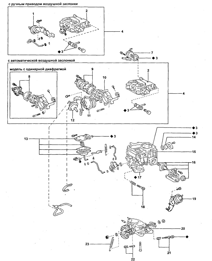
1 - position regulator ("switch") damper position (SW),
2 - carburetor cover (float chamber cover),
3 - gasket,
4 - top cover of the carburetor (float chamber cover) assembled,
5 - version with manual air damper,
6 - option with automatic air damper,
7 - valve of the unbalance system of the float chamber (OVCV),
8 - air damper switch (SW) (single aperture option),
9 - air damper switch (SW) (double aperture option),
10 - thermostat housing,
11 - spring housing (air damper coil heater),
12 - switch of the cam of the system for increasing the idle speed (FICB),
13 - pneumatic actuator of the throttle valve of the secondary chamber,
14 - sight glass,
15 - carburetor body,
16 - accelerator pump,
17 - insulating gasket,
18 - adjusting screw for normal idle speed,
19 - opening mechanism or (manipulator) throttle,
20 - body of mixing chambers ("carburetor flange"),
21 - quality adjustment screw (composition) mixtures for normal idling,
22 - adjusting screw for increased idle speed when the engine warms up,
23 - accelerator return spring,
♦ - a part that cannot be reused.
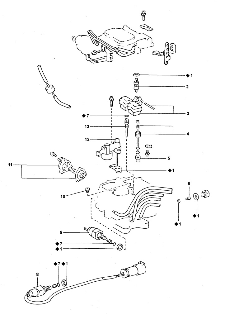
1 - gasket,
2 - needle valve,
3 - float,
4 - economizer drive piston,
5 - economizer valve,
6 - main fuel jet of the primary chamber,
7 - annular sealing gasket,
8 - solenoid valve for cutting off the fuel supply of the primary chamber,
9 - solenoid valve for cutting off the fuel supply of the secondary chamber,
10 - main fuel jet of the secondary chamber,
11 - optional (auxiliary) accelerator pump (AAR),
12 - small diffuser of the secondary chamber,
13 - idle jet,
♦ - a part that cannot be reused.
The float chamber has an unbalance valve 1 (float chamber ventilation valve), informing the float chamber with the atmosphere after the engine stops. This prevents fuel vapors from entering the carburetor air path and makes it easier to start a hot engine.
Structurally, the carburetor consists of three main assembly units (see fig. "Carburetor parts" on page 36): carburettor cap assembly 4 (air inlet or float chamber cover), carburetor bodies 15 and mixing chamber bodies 20 ("flange" carburetor). A gasket 3 is installed between the first two assembly units, and an insulator 17 is installed between the second two. The carburetor cover assembly 4 includes (see fig. "Carburetor parts" on page 36): cap body 2, needle valve and float (see 3 and 2 in fig. page 37), manual or automatic air damper, ventilation valve ("imbalances") 7 float chamber. The automatic air damper drive includes: an air damper coil heater 11, a thermostat housing 10 and a cam position switch 12 that controls an increased idle speed when the engine warms up.
In the carburetor body assembly or on the body are (see fig. "Carburetor parts" on page 36): diffusers, sight glass 14 of the float chamber, fuel and air jets, economizer, corrector of the composition of the idle mixture of a warm engine, main accelerator pump 16, additional accelerator pump (see 11 in fig. page 37), the diaphragm mechanism of the pneumatic actuator of the throttle valve of the secondary chamber 13, the mechanism for opening the throttle valve or the throttle valve manipulator 19, the solenoid valves for shutting off the fuel supply (see 8 and 9 in fig. page 37).
The carburetor mixing chamber assembly includes (see fig. "Carburetor parts" on page 36): throttle valves of the primary and secondary chambers, screw 21 for adjusting the composition of the mixture at idle, screw 22 for adjusting the speed of normal idle, screw 35 for adjusting the high idle speed when the engine is warming up, the throttle actuator lever of the primary chamber.
On the carburetor body, a diaphragm mechanism 1 of the automatic throttle actuator of the secondary chamber is placed as a separate unit.