



Removal
1. Remove the gearbox.
Note: Draining the gearbox oil is not necessary.
2. Remove the clutch housing assembly and the clutch driven disc.
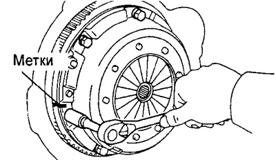
a) Apply alignment marks on the clutch housing and flywheel.
b) Loosen each set bolt one turn at a time to ensure that the spring is completely released from preload.
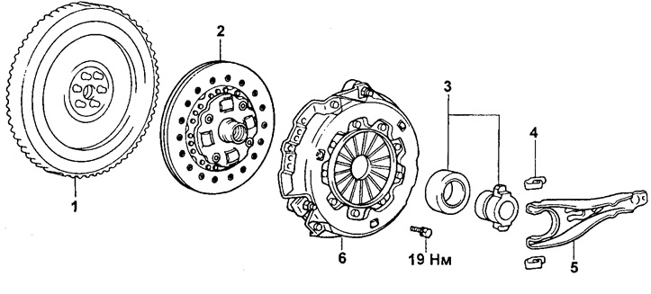
Clutch.
1 - Flywheel,
2 - Clutch slave disc,
3 - Release bearing,
4 - Clamp,
5 - Clutch release fork,
6 - Clutch housing assembly with diaphragm spring.
c) Unscrew all mounting bolts completely and remove the clutch housing and driven clutch disc.
Note: Do not drop the disc.
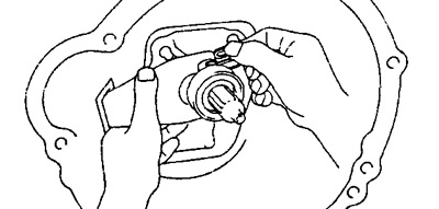
3. Remove the release bearing and release fork.
a) Remove the clamp and take out the release bearing.
b) Remove the clutch release fork and boot.
Checking the details
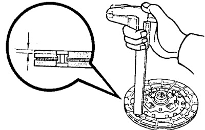
1. Inspect the clutch disc for wear or damage and use calipers to measure the depth of the rivet heads.
- Minimum depth of rivet heads - 0.3 mm
2. Inspect the clutch driven disc and check the radial runout.
- Maximum runout - 0.8 mm
Note: If the runout is excessive, replace the disc.
3. Inspect the flywheel for runout.
- Maximum runout - 0.2 mm
Note: If runout is excessive, replace the flywheel.
4. Inspect the gearbox input shaft bearing.
While turning the bearing by hand, simultaneously apply force to it in the axial direction.
Note: If the bearing is seizing or exhibits increased resistance, replace the bearing.
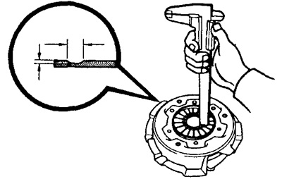
5. Using a caliper, measure the diaphragm spring and determine its wear by depth and width.
Limit:
- by depth - 0.6 mm
- by width - 5.0 mm
Note: If necessary, replace the clutch housing assembly with the diaphragm spring.
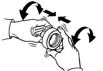
6. Check the release bearing. Rotate the bearing with your hands, applying force to it in the direction of rotation.
Note: If the bearing is seizing or has increased resistance to rotation, replace the release bearing.
Note: The bearing is lubricated for life and does not require cleaning or lubrication.
Installation
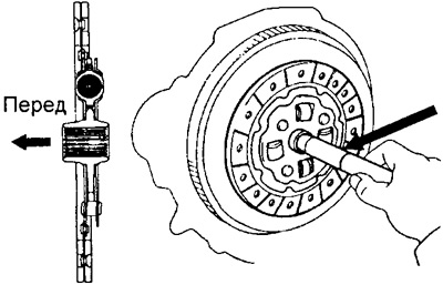
1. Using a drift, install the clutch disc onto the flywheel.
2. Install the clutch cover.
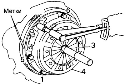
a) Align the marks made on the clutch housing and flywheel during disassembly.
b) Tighten the clutch housing mounting bolts in the sequence shown in the figure.
- Tightening torque - 19 Nm
3. Apply grease (NLGI grade 2) to the surface of the following parts:
Clutch release forks and release bearing at their contact points.
Clutch release forks and slave cylinder rod at their contact points.
At the ball joint point of the clutch release fork.
On the splines of the primary shaft of the gearbox.
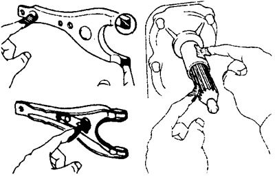
4. Apply MP type grease as shown in the figure.
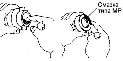
5. Install the boot, clutch release fork and release bearing.
6. Install the gearbox.
The original publication can be found on the website ToyotaMan