



- 1. Electronic fuel injection. The control unit receives signals from various sensors that transmit data on the operating mode, including pressure in the intake manifold, intake air temperature, coolant temperature, engine speed and engine acceleration or braking. This data is evaluated in the microprocessor to determine the exact injection moment for the formation of an optimal air-fuel mixture.
- 2. Electronic ignition timing control. The electronic control unit is programmed with data for the optimum ignition timing. With the help of the various sensors mentioned above, the spark is generated by the spark plugs at the right moment.
- 3. Diagnostic function. The control unit registers each failure or malfunction in the system and lights a warning lamp on the dashboard. At the same time, the microprocessor remembers the failure. Thanks to this, the failure is immediately determined at the service station.
- 4. Failure monitoring. In the event of a microprocessor failure, individual functions are performed by a backup circuit, allowing the vehicle to be driven to the nearest service station. In this case, a warning lamp on the instrument panel lights up.
Figure 138 shows a diagram of the injection system on a 2.0L engine, indicating the position and connections of individual components. The figure shows a system operating with a catalytic converter as it is installed on most vehicles. Similar components are used on a 1.6L engine operating with a catalytic converter.
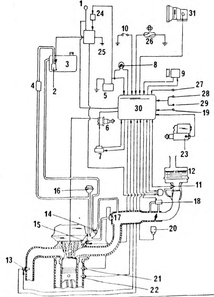
Fig. 138. Electrical and fuel connection diagram of the fuel injection device of the 2.0 l engine: 1. Ignition switch; 2. Fuel pump; 3. Fuel tank; 4. Fuel filter; 5. Battery; 6. Ignition distributor; 7. Ignition coil; 8 Warning lamp "Check"; 9. Air conditioning compressor; 10. Control socket (T-E1); 11. Supply air temperature sensor; 12. Air filter; 13. Lambda probe; 14. Fuel pressure regulator; 15. Injector; 16. Pressure damper; 17. Cold start injector; 18. Idle speed control valve (additional air); 19. Fuel system control switch; 20. Throttle position sensor; 21. Cold start injector time relay; 22. Coolant temperature switch; 23. Starter; 24. Main relay; 25. Electrical circuit disconnect relay; 26. Speed sensor; 27. To the brake lights; 28. Headlight switch; 29. Rear window heating switch; 30. Electronic control unit; 31. Neutral switch sensor
The text is quoted from the source website: www.ToyotaMAN.ru