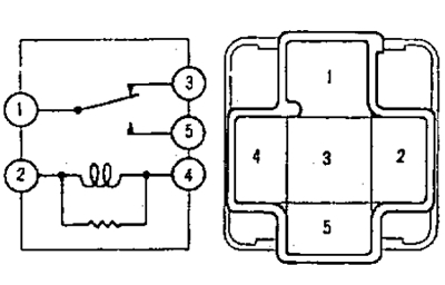
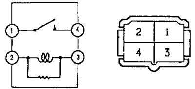
A) Check for continuity between terminals "2" And "4".
b) Check for continuity between terminals "1" And "3".
V) Check for continuity between terminals "1" And "5".
G) Check for continuity between terminals "1" And "5" and lack of conduction between the terminals "1" And "3" relay when battery voltage is applied to the terminals "2" And "4".
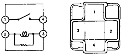
2. Check fan relay #3.
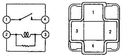
A) Check for continuity between terminals "2" And "3".
b) Check for continuity between terminals "1" And "4".
V) Check for continuity between terminals "1" And "4" relay when battery voltage is applied to the terminals "2" And "3".
3. Checking the EX-HI relay (button type panel).
A) Check for continuity between terminals "2" And "3".
b) Check for continuity between terminals "1" And "4".
V) Check for continuity between terminals "1" And "4" relay when battery voltage is applied to the terminals "2" And "3".
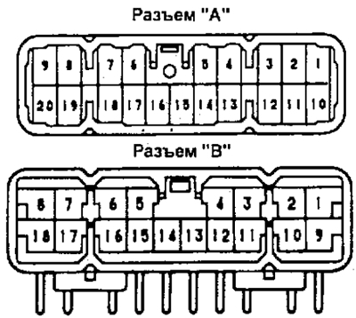
4. Checking the fan speed switch for the heater and air conditioning system (lever type panel).
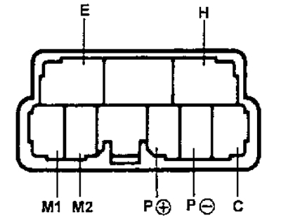
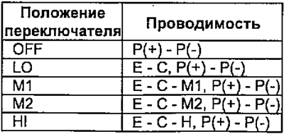
Check for continuity between the terminals at various fan speed switch settings.
5. Checking the relay for increasing the idle speed when the heater is turned on (for 2C with keypad type).
A) Check for continuity between terminals "2" And "3".
b) Check for continuity between terminals "1" And "4".
V) Check for continuity between terminals "1" And "4" relay when battery voltage is applied to the terminals "2" And "3".
6. Checking the operation of the fan motor.
A) Connect the battery to the terminals "1" (+) And "2" (-) connector, check the smooth rotation of the rotor.
b) Measure the motor current.
- Rated current - less than 3 A
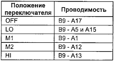
7. Checking for continuity between connector pins "A" And "IN" control panels (button type panel) at different positions of the fan speed switch.