
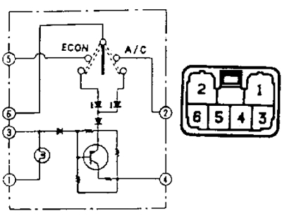
Check for continuity between the terminals at various switch positions.
2. Checking for continuity between connector pins "A" And "IN" control panels (button type panel) at different positions of the system switches.
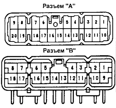
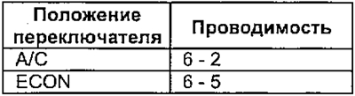
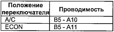
A) Checking for continuity between connector pins "A" And "IN" control panel at different switch positions "A/C - ECON".
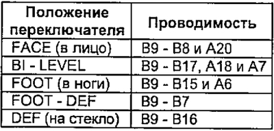
b) Checking for continuity between connector pins "A" And "IN" control panel at different positions of the blower direction switch.
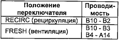
V) Checking for continuity between connector pins "A" And "IN" control panel at various positions of the air intake switch.
Except 4A-FE engines
G) (For 4A-FE engines). Check for continuity between terminals "A14" - "AT 6" control panel connector.
3. Checking the resistance of the temperature controller.
A) Measure resistance between leads "A8" - "B18" control panel connector.
- Resistance - 3 kOhm
b) Connect tester to terminals "B18" - "A9" control panel connector and measure the resistance between the terminals with the water valve switch in the MAX HOT and MAX COLD position.
- MAX HOT - 3 kOhm
- MAX COLD - 0 ohm
V) Verify that when the switch is switched from MAX COLD to MAX HOT, the resistance changes.