



Contents: 4A-FE, 5A-FE, 7A-FE ↓ 3S-FE ↓
The combined ignition unit was installed on engines 4A-FE (since 08.1994), 5A-FE, 7A-FE, 3S-FE.
4A-FE, 5A-FE, 7A-FE
1. Install the capacitor.
2. Install the distributor wire and wire holder.
3. (Besides Lean Burn) Install the switch by securing it with two screws and connecting the three wires to the terminals.
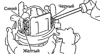
4. Install the ignition coil in the correct order,
a) Remove old sealant.
b) Apply fresh sealant to the contact surface of the ignition coil housing that mates with the surface of the ignition unit housing as shown in the figure.
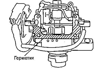
c) Install and secure the ignition coil with 4 screws.
5. Connect the wires to the ignition coil terminals, securing them with two nuts as shown in the figure.
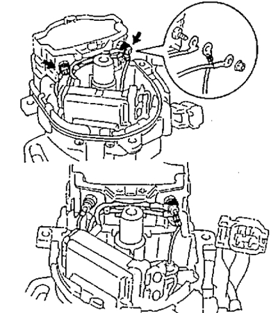
Besides Lean Burn
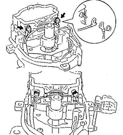
Lean Burn
Note:
- - When connecting the wires to the ignition coil, place the wires in the grooves provided on the side surface of the ignition coil.
- - Make sure that the wires do not touch the angular pulse sensor rotor or the housing of the integrated ignition unit.
6. Install the ignition coil dust deflector, first installing a new gasket under the cover of the combined ignition unit housing.
7. Install the distributor rotor.
8. Install the cover, securing it with 3 bolts.
3S-FE
Note: See corresponding drawings for A series engines.
1. Install the capacitor.
2. Install the ignition coil in the correct order.
a) Remove old sealant.
b) Apply fresh sealant to the contact surface of the ignition coil housing that mates with the surface of the ignition unit housing.
c) Install and secure the ignition coil with 4 screws.
5. Connect the wires to the ignition coil terminals, securing them with two nuts.
6. Install the ignition coil dust deflector, first installing a new gasket under the cover of the combined ignition unit housing.
7. Install the distributor rotor.
8. Install the distributor cap, securing it with 3 bolts.