
Note: terms "cold" And "hotter" state indicate the temperature of the windings:
- "cold" — from -10°C to +50°С
- "hot" — from +50°С to +100°C
These definitions are retained in the future also in relation to the inductive coils of the angular momentum sensors.
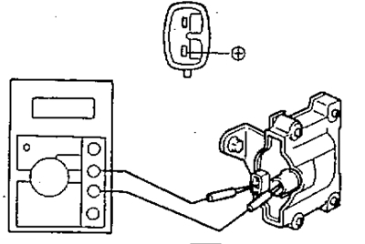
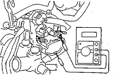
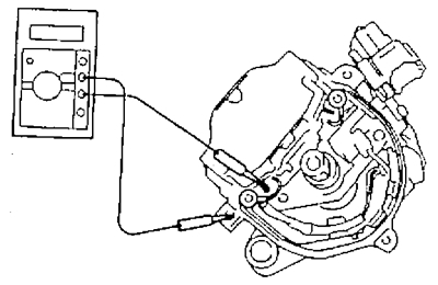
1. Check the resistance of the primary winding using an ohmmeter by connecting it to the ignition coil as shown in the figures.
4A-FE (until 08.1994), 3S-FE, 4S-FE
- in the cold» state - 0.36-0.55 Ohm
- when hot - 0.45-0.65 Ohm
4A-FE (from 08.1994), 5A-FE, 7A-FE
- V «cold» condition - 1.11-1.75 Ohm
- V «hot» condition - 1.41-2.05 Ohm
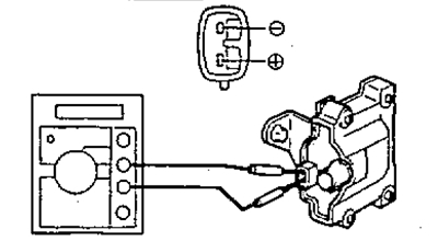
4A-FE (until 08.1994), 4S-FE
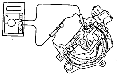
3S-FE
4A-FE (from 08.1994), 5A-FE, 7A-FE
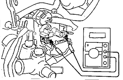
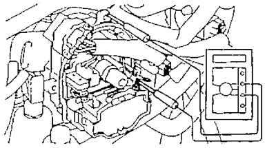
2. Check the resistance of the secondary winding using an ohmmeter by connecting it to the ignition coil as shown in the figures.
- V «cold» condition - 9.0-15.7 kOhm
- V «hot» condition - 11.4-18.4 kOhm
4A-FE (until 08.1994), 4S-FE
3S-FE
4A-FE (from 08.1994), 5A-FE, 7A-FE
If the resistance of any of the ignition coil windings does not correspond to the nominal value, replace it! those ignition coil.
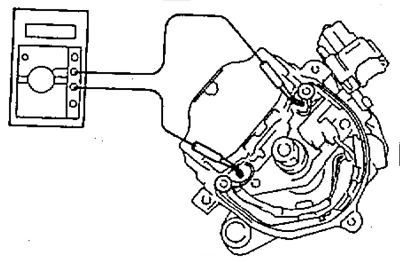
3. Using a megger, measure the resistance between the negative terminal of the ignition coil (-) and high voltage wire output!
- Rated resistance - not less than 10 MΩ
Otherwise, replace the ignition coil.
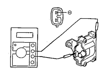
4A-FE (until 08.1994), 4S-FE
3S-FE
4A-FE (from 08.1994), 5A-FE, 7A-FE