
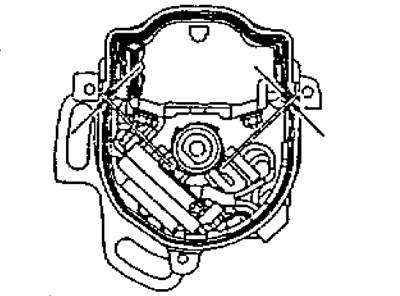
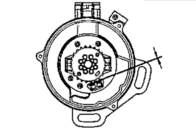
1. Using a feeler gauge, check the air gap between the teeth of the rotor of the angular impulse sensors and the protrusion of the core of the inductive coil of this sensor.
Note: multiple angle pulse sensors can be used in the ignition system (crankshaft angle sensor NE and camshaft angle sensors G, G1, G2), then similar measurements should be performed for each sensor.
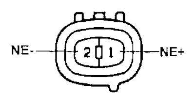
NE sensor (5A-FE)
NE sensor (4A-FE until 08.1994)
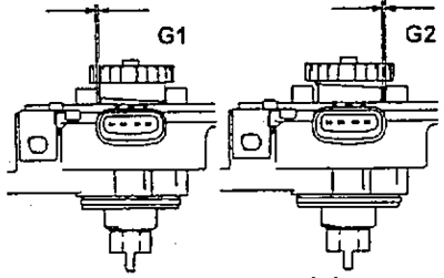
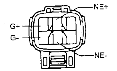
Sensors G1, G2 (4A-FE until 08.1994)
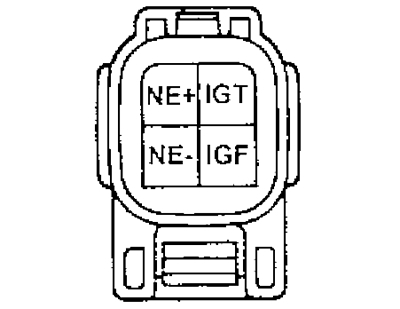
NE sensor (4S-FE)
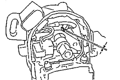
NE sensor (3S-FE)
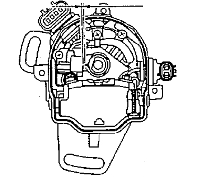
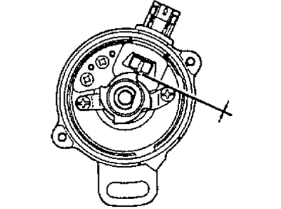
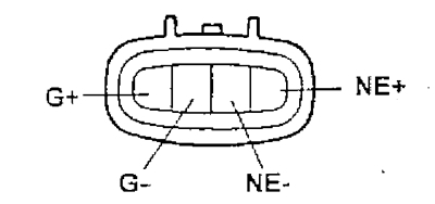
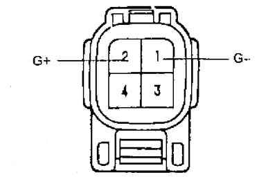
G sensor (3S-FE)
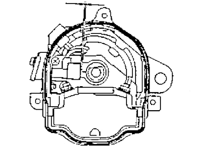
G sensors (4A-FE until 08.1994, 7A-FE)
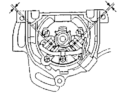
NE sensor (4A-FE until 08.1994, 7A-FE)
- Nominal air gap - 0.2-0.5 mm
If clearance is out of specification, replace distributor housing, distributor assembly, or integrated ignition housing (block contactless ignition system).
2. Using an ohmmeter, check the electrical resistance of the inductive coils of the crankshaft and camshaft angle pulse sensors. The ohmmeter connection diagrams are shown in the figures, and the pin numbers to which the ohmmeter must be connected, and the nominal resistance values of the inductive coils of the angular pulse sensors are given in the table "The value of the electrical resistance of the inductive coils of the sensors of angular impulses".
5A-FE
IN "cold" condition:
- NE (+) and NE (-) - 370-550 Ohm
IN "hot" condition:
- NE (+) and NE (-) - 475-650 Ohm
4A-FE (until 08.1994)
IN "cold" condition:
- G1 (+) - G1 (-) - 185-275 Ohm
- G2 (+) - G2 (-) - 125-235 Ohm
- NE (+) and NE (-) - 190-290 Ohm
IN "hot" condition:
- G1 (+) - G1 (-) - 160-235 Ohm
- G2 (+) - G2 (-) - 160-235 Ohm
- NE (+) and NE (-) - 190-290 Ohm
4A-FE (c 08.1994)
IN "cold" condition:
- G (+) - G (-) - 185-275 Ohm
- NE (+) and NE (-) - 370-550 Ohm
IN "hot" condition:
- G (+) - G (-) - 240-325 Ohm
- NE (+) and NE (-) - 475-650 Ohm
7A-FE
IN "cold" condition:
- G (+) and G (-) - 185-275 Ohm
IN "hot" condition:
- G (+) and G (-) - 240-325 Ohm
4S-FE
IN "cold" condition:
- NE (+) and NE (-) - 135-220 Ohm
IN "hot" condition:
- NE (+) and NE (-) - 175-255 Ohm
3S-FE
IN "cold" condition:
- G (+) - G (-) - 185-275 Ohm
- NE (+) and NE (-) - 370-550 Ohm
IN "hot" condition:
- G (+) - G (-) - 240-325 Ohm
- NE (+) and NE (-) - 475-650 Ohm

4A-FE (until 08.1994)
4A-FE (from 08.1994, except Lean Burn)
5A-FE
4S-FE
3S-FE
4A-FE (from 08.1994, except Lean Burn), 7A-FE
If the resistance is not within the specified limits, replace the entire valve assembly (housing of the integrated ignition unit).
3. Replace: distributor rotor, distributor cap and connect the distributor connector.