



Contents: Removal ↓ Installation ↓ Removal the generator from the…↓ Installation ↓ Removal the diesel generator ↓ Installation ↓
Generator brushes wear out quite slowly. On average, they wear out after 120,000 km of mileage. However, it is recommended to replace them in advance.
Depending on the car model, generators can be of different designs. Brush removal for all engines produced since 5/87 and diesel engines produced since 5/83 is performed without removing the generator.
Removal
Disconnect the ground (-) cable from the battery.
Warning: This will erase the entries in the trip computer memory. In particular, the fault entry and the radio receiver code. Before disconnecting the battery, read the section "Removal and installation the battery".
Petrol engines up to 4/87
Remove the generator.
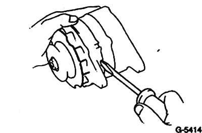
Remove the three screws and the covers from the drive side. Be careful not to damage the stator winding with the screwdriver (fig. G-5416).
Lightly clamp the generator rotor in a vice and loosen the central pulley mounting bolt. Remove the pulley together with the wing and spacer sleeve.
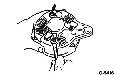
Remove the four nuts, two terminal insulators and the wire clamp. Then remove the rear rotor housing.
Remove the insulators from the stud supports.
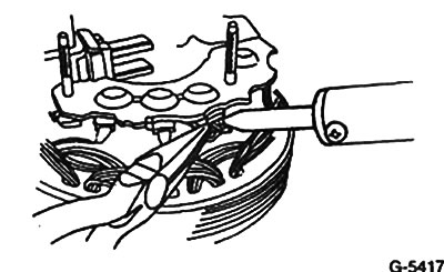
Unsolder the stator winding wire from the rectifier board. In doing so, clamp the wire with pliers to protect the rectifier from overheating.
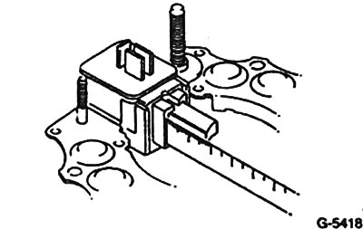
Replace the brushes if the protrusion length is 5.5 mm or less. To do this, unsolder the connecting multi-core wire.
Check the slip rings on the rotor for wear. Clean the rings if necessary.
Check the rotor bearings for ease of movement. Replace if necessary. The rear bearing is pressed on. It must be removed with a puller.
Installation
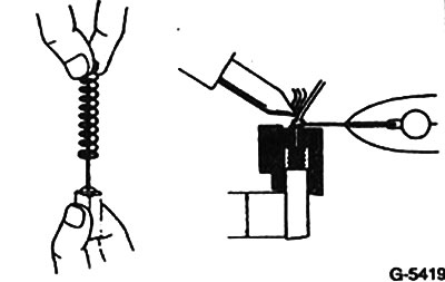
Insert the brush and spring into the brush holder and solder. The brush should protrude by 12.5 mm.
When soldering, clamp the connecting multi-core brush wire with pliers to prevent solder from getting on it.
Caution: When solder gets into the wire, it becomes hard, which leads to its failure.
After installation, check the ease of movement of the brushes in the brush holder.
Solder the wire connecting the stator to the rectifier board, making sure that the rectifier does not overheat.
Install the rear casing onto the generator rotor.
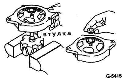
Install the drive side cover.
Install the impeller with the pulley and spring ring.
(The material is republished from an online website: toyotaman.ru)
Tighten the fastening nut to 60 Nm.
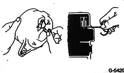
Assemble the generator housing. First bend the rectifier contact back so that it does not touch the rotor. At the same time, hold the brushes pushed in with a wire. There is a hole on the rear bearing cover for this purpose.
Fasten the body with three special screws.
Remove the wire holding the brushes and seal the hole with sealant.
Check the ease of rotation of the rotor.
Install the generator in place.
Removal the generator from the engine from 5/87
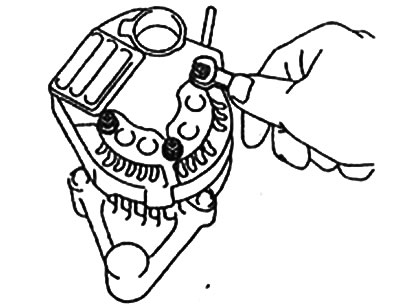
Remove three nuts and remove the back cover.
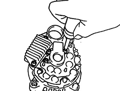
Remove 5 screws and brush holder and regulator.
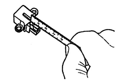
Replace brushes if their protrusion length is 4.5 mm or less.
Installation
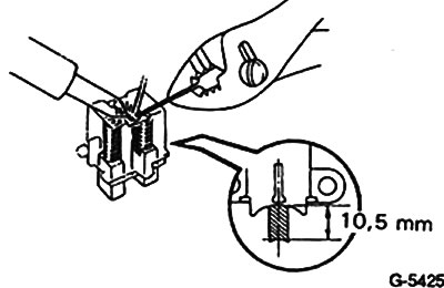
Insert the brush and spring and solder the joint. The brush should extend 10.5 mm.
Be careful not to let any solder come into contact with the stranded wire connecting the brush.
Caution: Solder will cause the wire to become stiff, preventing the brush from working properly.
Check the ease of movement of the brush in the brush holder.
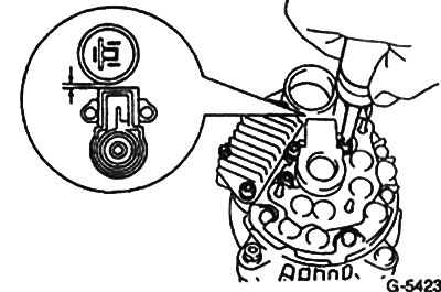
Close the brush holder cover (3 screws). Make sure that the gap between the holder and the plug is at least 1 mm.
Install and screw in the rear cover of the generator.
Removal the diesel generator
Note: Diesel generators are partially installed in the same way as petrol engines from 5/87. Check this using the following figures.
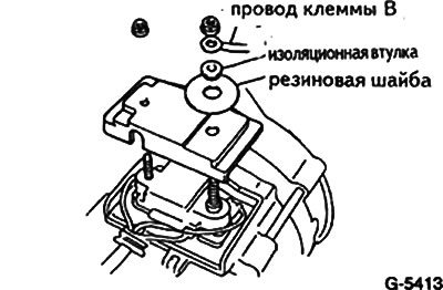
Disconnect the wire and remove the cover.
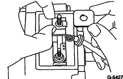
Version without electronic regulator: Disconnect the insulating gasket and connecting wire. Remove the nut and take out the brush holder (fig. G-5427).
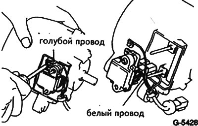
Version with electronic regulator: Loosen the screw on the brush holder and disconnect the blue wire. Remove the regulator and then disconnect the white wire.
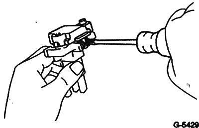
Remove two screws and remove the electronic unit from the brush holder.
Replace brushes if they protrude 5.5 mm or less.
Installation
Insert the brushes and springs into the brush holder and solder the brushes. The brush should extend 20 mm.
Check the ease of movement of the brushes in the brush holder.
Install the assembled generator in place.
Connect the ground (-) cable to the battery.
Set the time on the clock, if there is one. Enter the code into the radio receiver.