



Contents: Removal brake pads ↓ Checking brake pads ↓ Checking the brake disc and brake…↓ Measuring the thickness of the brake…↓ Measuring Brake Disc Runout ↓ Assembly ↓
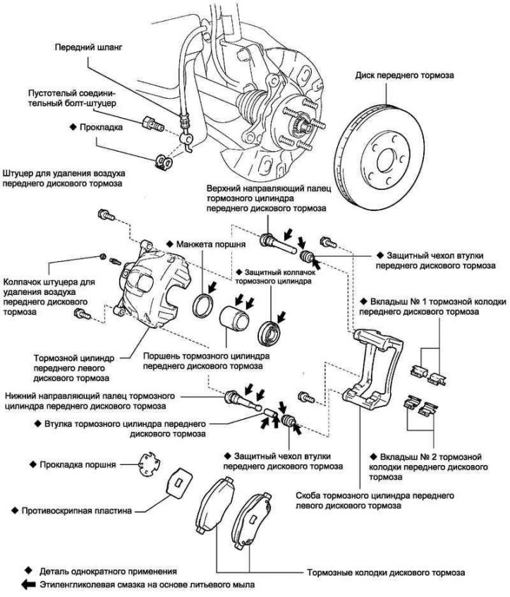
Fig. 6.25. Front brake components
Removal brake pads
Drain the brake fluid.
Caution: When replacing brake pads, always replace the inner pads, outer pads and pad covers as a set.
Remove the front wheel and temporarily secure the wheel rim with two nuts.
Loosen the bolt and disconnect the brake hose bracket.
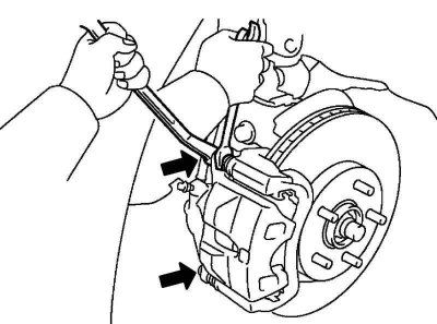
Fig. 6.26. Loosening the caliper mounting bolts
Holding the guide pins, unscrew the caliper mounting bolts (Fig. 6.26).
Raise the caliper and secure it with wire.
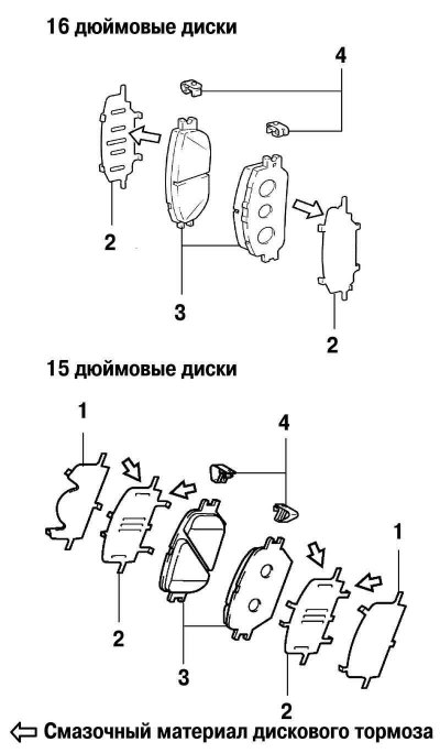
Fig. 6.27. Brake pad components: 1 – anti-squeak plate; 2 – anti-squeak gasket; 3 – brake pads; 4 – brake pad wear indicators
Remove two anti-squeak springs, two brake pads, two anti-squeak pads holding the plate liners (Fig. 6.27).
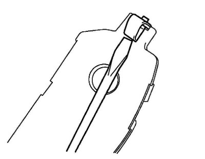
Fig. 6.28. Removing the brake pad wear indicators
Using a thin-bladed screwdriver, remove the brake pad wear indicators (Fig. 6.28).
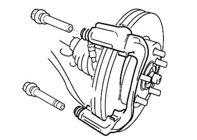
Fig. 6.29. Removing the guide pins from the caliper
Remove the guide pins from the caliper (Fig. 6.29).
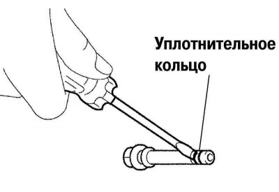
Fig. 6.30. Removing the sealing ring from the guide pin
Using a thin-bladed screwdriver, remove the sealing rings from the guide pins (Fig. 6.30).
Caution! When removing the seal, do not damage the guide pin housing.
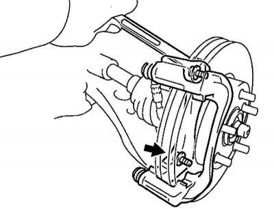
Fig. 6.31. Removing the caliper
Unscrew the caliper housing mounting bolts and remove the caliper (Fig. 6.31).
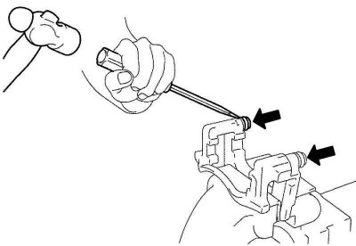
Fig. 6.32. Removing the guide pin dust boots
Holding the caliper in a vice with soft jaws, use a screwdriver and hammer to remove the guide pin dust boots (Fig. 6.32).
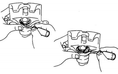
Fig. 6.33. Removing the brake cylinder boot
Using a screwdriver, remove the brake cylinder boot spring ring and boot (Fig. 6.33).
Place a rag between the piston and the cylinder.
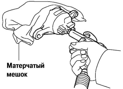
Fig. 6.34. Removing the piston from the cylinder
Using compressed air, remove the piston from the cylinder (Fig. 6.34).
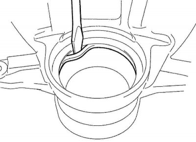
Fig. 6.35. Removing the oil seal
Using a screwdriver, remove the seal (Fig. 6.35).
Checking brake pads
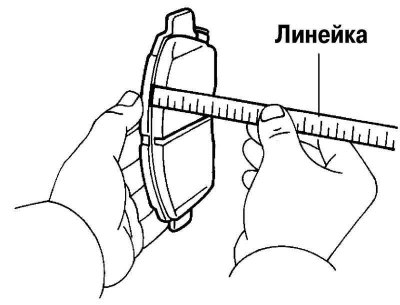
Fig. 6.36. Measuring the thickness of brake shoe linings
Measure the thickness of the brake shoe linings with a ruler (Fig. 6.36).
- Standard thickness: 12 mm.
- Minimum thickness: 1.0 mm.
Checking the brake disc and brake components
Check the inner cylinder walls for corrosion, wear and damage. Replace the cylinder body if necessary. Minor defects caused by corrosion or foreign particles can be removed by sanding the surface with fine emery cloth. Replace the cylinder body if necessary. Check for wear, cracks and damage. Replace the component if necessary. Check the piston surface for corrosion, wear and damage. Replace the component if necessary. Check the guide pin and guide pin boot for corrosion, wear and damage. Replace the component if necessary. Check the brake disc surface for uneven wear, cracks and serious damage.
Measuring the thickness of the brake disc
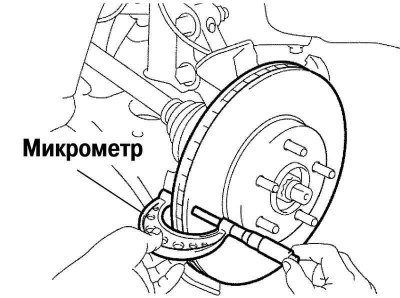
Fig. 6.37. Measuring the thickness of the brake disc
Using a micrometer, measure the thickness of the brake disc (Fig. 6.37).
- Standard thickness: 28 mm
- Minimum thickness: 26 mm
Replace the disc if the disc thickness is less than the minimum allowable.
Measuring Brake Disc Runout
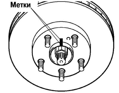
Fig. 6.38. Applying marks to the hub axle sleeve and brake disc
Apply marks to the brake disc and the wheel hub axle bushing (Fig. 6.38).
Secure the brake disc to the wheel hub using wheel nuts (in 2 or more places).
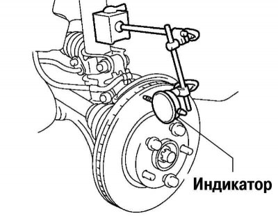
Fig. 6.39. Checking the disc runout using an indicator
Check the runout with an indicator (Fig. 6.39).
- Measuring point: 10 mm from the outer edge of the disc.
- Maximum runout: 0.05mm or less.
Caution: Before taking measurements, make sure that the axial play is 0 mm.
If the runout is significant, find the point of minimum runout by successively shifting the installation position of the brake disc on the hub by one hole.
Assembly
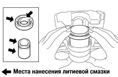
Fig. 6.40. Installing the seal in the piston
Apply lithium rubber grease to the piston seals and install them into the cylinder body (Fig. 6.40).
Caution: Do not apply too much force when installing to avoid damaging the parts.
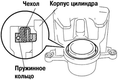
Fig. 6.41. Installing the spring ring and brake cylinder boot
Install the brake cylinder boot spring ring and boot (Fig. 6.41).
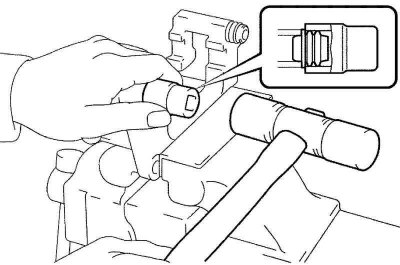
Fig. 6.42. Installing the guide pin dust boots
Using a socket wrench (19 mm) and a hammer, install the guide pin dust boots (Fig. 6.42).
Pre-lubricate the dust boots with lithium grease.
Install the brake cylinder housing onto the brake disc and tighten the mounting bolts.
Tightening torque: 103 Nm.
Install the guide pins.
Install the brake pads.
Install the caliper.
Tighten the mounting bolts.
Tightening torque: 34 Nm.
Install the brake hose and tighten the mounting nut.
Tightening torque: 29 Nm.
Pour brake fluid into the tank.
Check if brake fluid is leaking from the master cylinder.
Check the brake system pipes and hoses.
Bleed the brakes.
Install the wheels.