
Checking the mixture correction system (when using the portable diagnostic tool II)
Connect the Handheld Diagnostic Tool II to the DLC3 connector.
Turn on the ignition (ON).
Select instrument mode: Powertrain/ Engine and ECT/ Data List/ O2S B1 S2.
Checking the mixture correction system (in the absence of a portable diagnostic tool II)
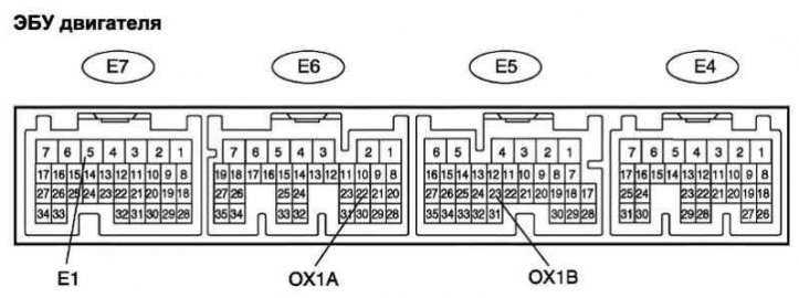
Pic. 2.583. ECU terminals
Connect a voltmeter to terminals E5–23 (OX1 B) and E7–5 (E1) and to terminals E6-22 (OX1 A) and E7–5 (E1) ECU block (pic. 2.583).
Attention! Connect the instrument wires to the connector (from the wiring harness side), connected to the engine ECU.
Warm up the heated oxygen sensor at 2500 rpm–1 within 2 min.
At an engine speed of 2500 min–1 instrument readings should vary between 0 and 1 V.
Note. The output voltage changes at least 8 times in 10 s.
Attention! Check as soon as the sensor warms up.
Attention! If the change in voltage at the output of the sensor does not meet the above requirements, then it is necessary to warm up the oxygen sensor again.
Attention! If the change in output voltage is still not normal after rewarming the sensor, check for DTCs.
Checking the engine speed at which the fuel supply stops
Increase the engine speed to at least 3500 min–1.
Use a stethoscope to check the sound of the injector.
Verify that when the throttle lever is released, the injector sound stops momentarily and then resumes.
Checking the evaporative emission system
Check system operation.
Connect the Handheld Diagnostic Tool II to the DLC3 connector.
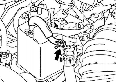
Pic. 2.584. Disconnecting the vacuum hose
After starting the engine, disconnect the vacuum hose, as shown in Figure 2.584.
Select instrument mode: Powertrain/ Engine and ECT/ Active Test/ Purge VSV.
Make sure that the vacuum control valve inlet (VSV) there is a vacuum.
Complete Diagnostics in Active Mode (Active Test) and connect the hose for the removal of fuel vapors.
Select instrument mode: Powertrain/ Engine and ECT/ Data LIst/ EVAP VSV.
Warm up the engine and test drive to make sure the VSV opens and closes.
Visual inspection of hoses, connections and seals
Do an external inspection.
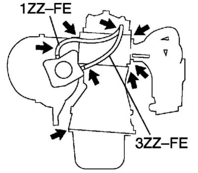
Pic. 2.585. Checked engine components
Check up, whether in the knots of the engine specified in drawing 2.585 leaks, cracks and other damages.
Note. Leaks at the connection points of the oil level sensor, oil filler cap, positive crankcase breather hose, and other parts can interfere with the operation of the engine. A disconnection, loose connection, or cracks in the intake system between the throttle body and cylinder head can cause air to enter the system and cause engine malfunction.
Eliminate the defects found during inspection of the engine.