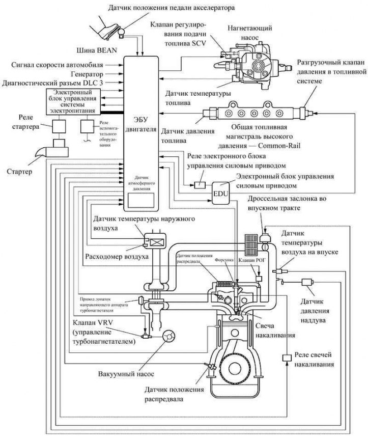
Pic. 2.93. Scheme of the engine control system 1СD-FTV
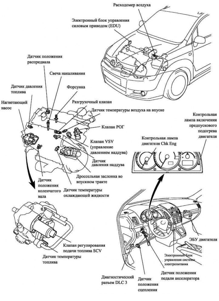
Pic. 2.94. Location of the main components of the 1CD-FTV engine control system
General information
The 1CD-FTV engine control system consists of the main components listed in Table 2.14.
Table 2.14. The main components of the 1CD-FTV engine control system
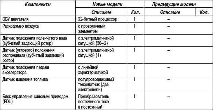
Engine ECU
The engine ECU is based on a 32-bit processor.
Crankshaft position sensor
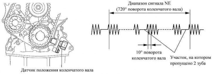
Pic. 2.95. crankshaft position sensor
The crankshaft drive rotor has 34 teeth and a section where 2 teeth are missing. The crankshaft position sensor sends a signal every 10°, and top dead center is determined from the area with missing teeth.
Camshaft position sensor
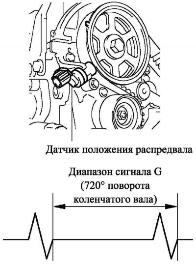
Pic. 2.96. Camshaft position sensor
To determine the position of the camshaft, there is a protrusion on the master rotor, with which 1 pulse is generated for every two revolutions of the crankshaft.
Accelerator pedal position sensor
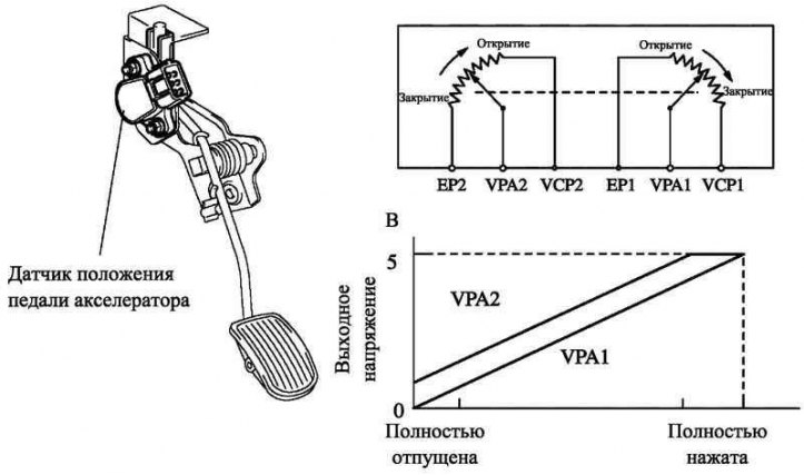
Pic. 2.97. Accelerator pedal position sensor
A return lever is provided to forcibly return the accelerator pedal position sensor lever to the fully closed position. The accelerator pedal switch is excluded.
The accelerator pedal position sensor converts the pedal stroke into electrical signals with two different characteristics and transmits them to the engine ECU. The VPA1 signal has a linear characteristic and is generated throughout the entire stroke of the accelerator pedal. The VPA2 signal has a biased voltage characteristic.
Fuel pressure sensor
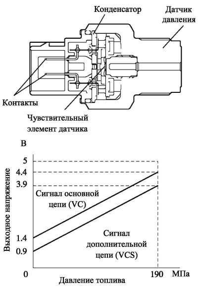
Pic. 2.98. Fuel pressure sensor
A fuel pressure sensor is installed in the Common-Rail common rail, which sends a signal to the engine ECU. The ECU maintains the optimum fuel pressure.
The fuel pressure sensor includes two circuits (basic and additional), whose signals are continuously monitored by the engine ECU. This ensures a high pressure detection accuracy and therefore a high control reliability.
Fuel Injection Control
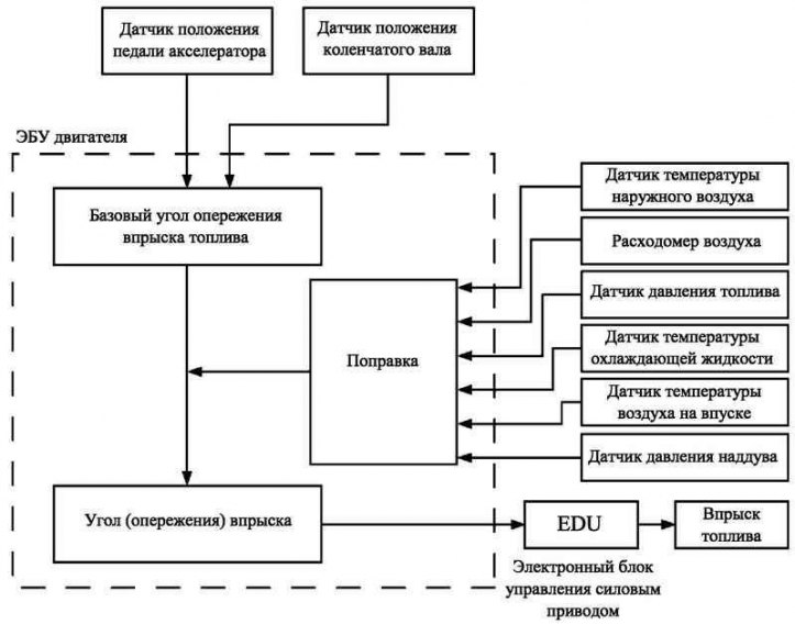
Pic. 2.99. Fuel Injection Volume Control Flow Diagram
Figure 2.99 shows the scheme by which the volume of fuel injection is controlled.
Fuel Injection Advance Adjustment
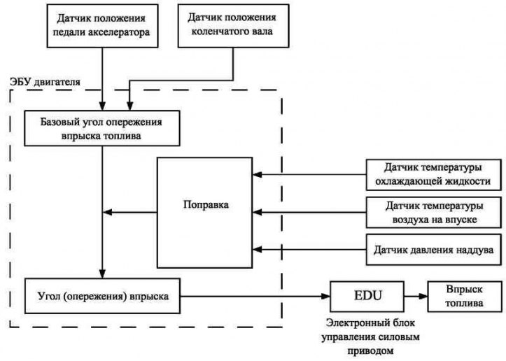
Pic. 2.100. Flowchart for fuel injection advance adjustment
Figure 2.100 shows a diagram by which the fuel injection advance angle is controlled.
Fuel pressure regulator
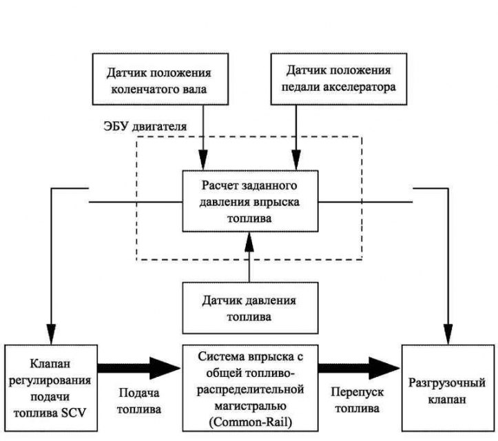
Pic. 2.101. Fuel Pressure Regulator Block Diagram
The engine ECU determines the target injection pressure (30–135 MPa) based on the signals of the accelerator pedal position sensor and the crankshaft position sensor, depending on the engine operating mode.
To control the fuel pressure, signals are sent to the fuel control valve (SCV) injection pump, which regulates the amount of fuel supplied. In parallel, control signals are sent to the unloading valve of the common fuel distribution line, which regulates the amount of fuel drained into the return line. The ECU controls the coincidence of the pressure determined by the fuel pressure sensor with the set injection pressure.
Fuel supply
To regulate the amount of fuel supplied by the charge pump to the common rail, the engine ECU controls the opening of the fuel control valve (SCV). Thus, the fuel pressure in the common rail is maintained in accordance with the set value.
Fuel control valve (SCV) open a little
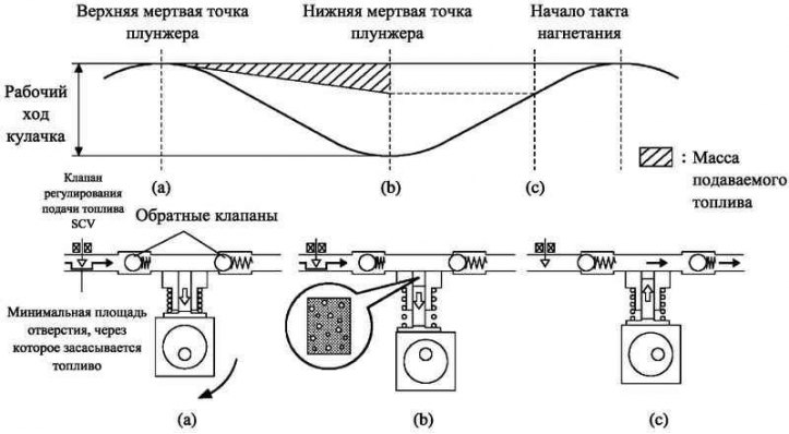
Pic. 2.102. The scheme of the SCV valve when opened a small amount
- a. With a slight opening of the fuel control valve, the area of the hole through which fuel is sucked in is minimal. The amount of injected fuel is also minimal.
- b. The plunger makes a full stroke, however, the amount of fuel sucked in is small due to the narrowed hole. The geometric volume of the pump cavity exceeds the volume of fuel sucked in, as a result, a vacuum is created in the chamber.
- c. Fuel injection starts when the fuel supply pressure becomes higher than the common rail pressure.
Fuel control valve (SCV) open to a large extent
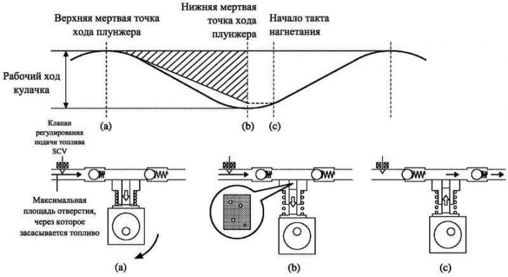
Pic. 2.103. The scheme of the SCV valve when opened to a large value
- a. When the fuel control valve is opened to a large extent, the area of the orifice through which fuel is drawn in is maximum. The volume of injected fuel is also maximum.
- b. The plunger makes a full stroke, and the volume of fuel sucked in increases, because. hole area is maximum.
- c. Fuel injection starts when the fuel supply pressure becomes higher than the common rail pressure.
Bypass fuel
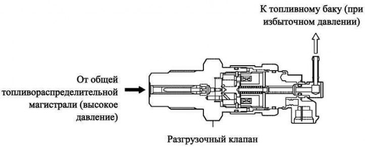
Pic. 2.104. The scheme of the bypass valve
When the pressure in the common fuel line exceeds the set value, the engine ECU bypasses fuel into the tank by opening the unloader valve. Thus, a predetermined pressure is maintained in the common fuel distribution line.
Fuel pre-injection adjustment
The pilot injection is performed before the main fuel injection and is designed to make the start of the combustion process smooth and reduce the noise level during engine operation.
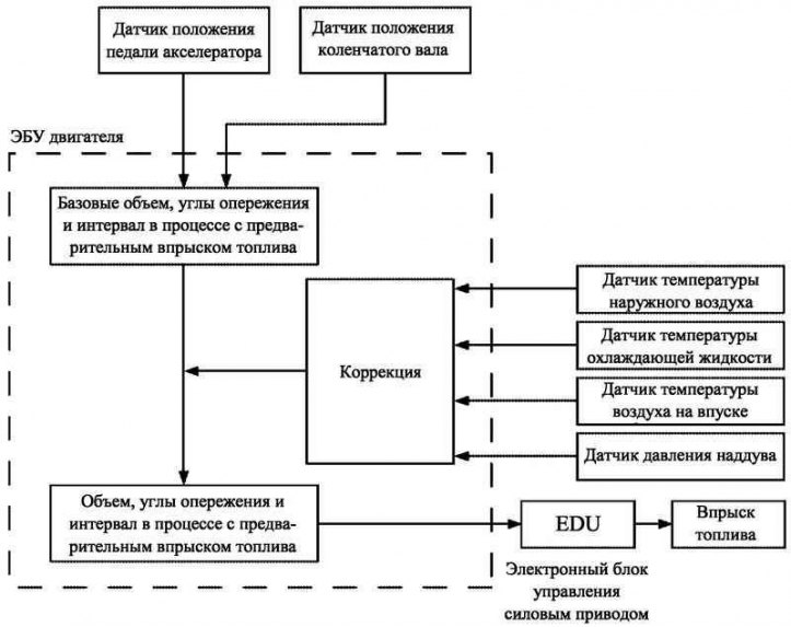
Pic. 2.105. Block - scheme for adjusting the preliminary fuel injection
Figure 2.105 shows a diagram that regulates the volume, lead angle and interval (between pilot and main fuel injection) in a pre-injection process.
Idling engine crankshaft speed controller
The engine ECU calculates the engine speed depending on the engine operating parameters and determines the amount of fuel injected to maintain the set idle speed.
To increase the efficiency of the heater when the engine is cold, the idle engine speed is increased when the corresponding switch is turned on.
Exhaust gas recirculation control unit (HORN)
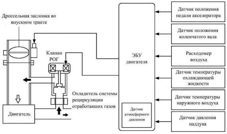
Pic. 2.106. Block - scheme for adjusting the exhaust gas recirculation system
Depending on the engine operating mode, the electronic unit simultaneously controls the EGR valve and controls the fuel supply using a stepper motor. In this way, the volume of recirculated exhaust gases is regulated.
Differences (from previous models)
Accordingly, the boost pressure control valve is excluded from the design (VRV) EGR and actuator (VSV) (to turn off recirculation).
Boost pressure regulator
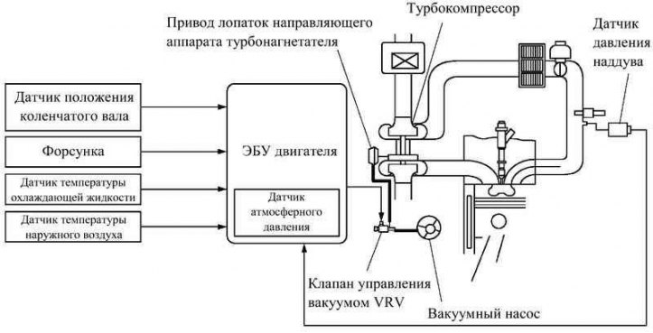
Pic. 2.107. Block diagram of the boost pressure regulator
boost pressure (intake manifold pressure) is regulated by changing the area of the nozzle located behind the turbine. The area of the nozzle is controlled directly by a drive connected to it. The actuator is controlled by vacuum, which is regulated by the VRV valve according to signals received from the engine ECU.
The engine ECU calculates the optimal boost pressure value depending on the engine operating mode (engine speed, injected fuel volume, atmospheric pressure and coolant temperature) and adjusts the flow area of the guide nozzle so that the pressure recorded by the boost pressure sensor corresponds to the calculated value.
Starter control function «Semi-automatic start»
How the starter control function works «Semi-automatic start» on the 1CD-FTV engine is similar to those used on the 1ZZ-FE and 3ZZ-FE engines.
Principle of operation
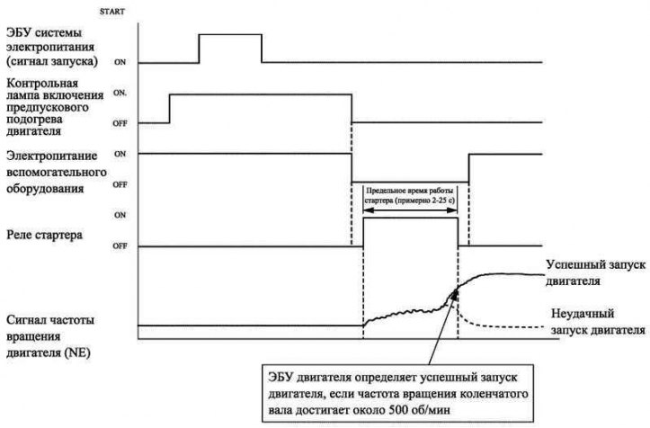
Pic. 2.108. Starter control function diagram
As shown in the diagram in Figure 2.108, when the engine ECU receives the start signal (STSW) from the power ECU, at the same time that the engine preheating warning light turns off, the engine ECU sends STAR and ACCR signals to the power ECU. The latter, in turn, sends a signal to the starter relay to start the engine. If the engine is already running, the engine ECU does not supply the STAR and ACCR signals to the power ECU. In this case, the starter does not turn on.
In addition, if the engine ECU repeatedly receives a start signal from the power ECU while the engine preheat warning lamp is on, it outputs the STAR and ACCR signals. The power supply ECU in turn sends a signal to the starter relay to start the engine.
After turning on the starter and after the engine speed exceeds approximately 500 min–1, the engine ECU detects that the engine is running and disengages the starter.
If the engine has a fault and does not start, the starter will operate for the maximum allowable time, after which it will automatically disengage. The maximum starter running time is approximately 2 to 25 seconds, depending on the coolant temperature. If the coolant temperature is very low, the starter runs for about 25 seconds, and when the engine is warm enough, the starter runs for no more than 2 seconds.
To avoid operation of auxiliary electrical equipment with unstable voltage during engine start, the system cuts off power to auxiliary equipment during this time.
The system provides the following levels of protection:
- if the engine is already running, the starter will not turn on even if the ignition key is turned to the START position;
- even if the driver holds the key in the ignition switch in the START position, after the engine is started from half a turn, the engine ECU will turn off the starter when the engine speed reaches approximately 1200 rpm–1 or more;
- even if the driver holds the ignition key in the START position and the engine does not start, the engine ECU will turn off the starter after about 30 seconds;
- if the starter is engaged but no engine speed signal is detected, the engine ECU will immediately disengage the starter.
Oil change warning system
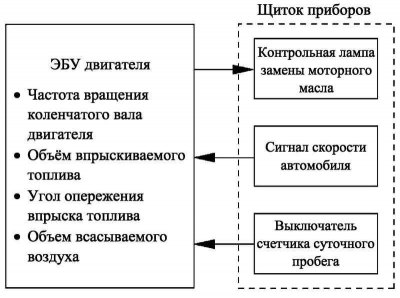
Pic. 2.109. Block diagram of the operation of the oil change warning system
An oil change warning system has been introduced. This system detects the deterioration of engine oil quality and warns the driver to change the engine oil and oil filter using a warning lamp. Thus, maintenance intervals are maintained (maximum 30,000 km), corresponding to the actual service life of the engine oil.
The engine ECU determines the degree of deterioration of the engine oil in an indirect way.
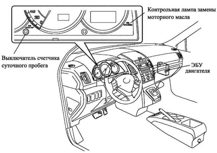
Pic. 2.110. The location of the system components in the car
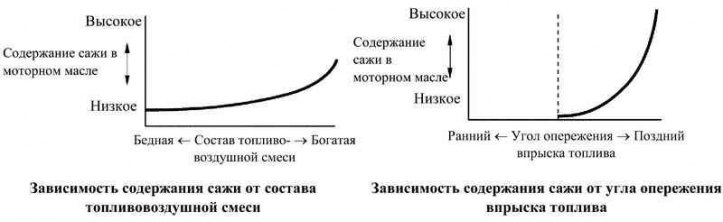
Pic. 2.111. Conditions for the formation of soot
Description of the system
The engine ECU determines the quality of the engine oil by its soot content. It calculates the amount of soot in the engine oil depending on the engine speed, fuel injection advance angle, fuel injection volume and air-fuel mixture composition. If the calculated soot content exceeds the specified value, the engine ECU turns on the engine oil change indicator lamp. Thus, this system warns the driver about the need to change the engine oil and oil filter.
The engine ECU turns on the engine oil change warning lamp not only when the soot content increases, but also every 30,000 km. Thus, the reliability of the system is increased.
Note. This system does not evaluate engine oil quality over time. Even if the engine oil change warning light does not turn on, change the engine oil and oil filter.
Setting the odometer to zero
You can reset the mileage recorded in the engine ECU memory, measured to turn on the oil change warning lamp, as follows:
- press the engine switch and turn on the ignition (IG-ON trigger system mode);
- make sure the LCD is in odometer mode (ODO). (In trip meter mode (TRIP) reset is not possible);
- press the engine switch and turn off the ignition (start system mode IG-OFF);
- while pressing the DIM ODO/TRIP button, press the engine switch to turn on the ignition (IG-ON trigger system mode), without depressing the clutch pedal. After turning on the ignition (IG-ON trigger system mode) hold the DIM ODO/TRIP button for at least 5 s. After resetting the liquid crystal display, release the DIM ODO / TRIP button;
- the oil change indicator lamp will turn off, and the LCD will display approximately 1 «000000»;
- make sure the LCD has switched to odometer mode (ODO);
- the procedure for resetting the odometer readings for changing the oil is completed.
Diagnostics
Diagnostic system type EURO-OBD (European system of on-board diagnostics), used on the 1CD-FTV engine, meets the requirements of European Union regulations.
If the engine ECU detects a problem, it diagnoses and logs the problem node. In addition, the check engine light on the instrument panel lights up «Chk Eng», to alert the driver.
Also, electronic codes are registered in the memory of the engine ECU (DTC).
These codes can be read using the microprocessor tester P.
All electronic DTCs comply with SAE requirements. Some DTCs have been broken down into smaller sub-sections than previously, with new DTCs assigned to the sub-sections.
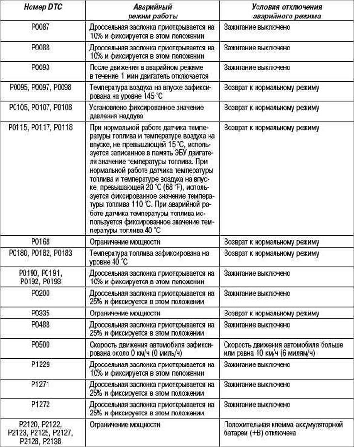
Emergency operation
Table 2.15 shows the conditions under which, when a malfunction is detected, the engine ECU turns off or puts the engine into emergency operation according to the data recorded in the memory.
Table 2.15. System operation in emergency mode