Check of the oil valve of management of the mechanism of change of phases of gas distribution assy
Check node operation.
Connect the handheld diagnostic tool II to the DLC3 diagnostic socket.
Turn the ignition ON (IG).
Turn on the portable diagnostic tool II.
Start the engine and warm it up.
Select instrument mode: Powertrain/ Engine and ECT/ Active Test/ VVT Control (Bank1).
By changing the operating modes of the oil valve for controlling the mechanism for changing the valve timing (OCV) using the handheld diagnostic tool II, check the engine speed.
Verification conditions
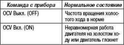
If the condition is not normal, check the variable valve timing control oil valve, wiring harness and engine ECU.
Checking the throttle body assembly
Evaluate the operation of the throttle actuator motor by ear.
Turn the ignition ON (IG).
While pressing the accelerator pedal, listen for the sound of the electric motor. The noise of rubbing parts should not be heard from the electric motor.
If rubbing noise is heard, check the throttle body, wiring harness and engine ECU.
Throttle position sensor test
Connect the handheld diagnostic tool II to the DLC3 diagnostic socket.
Turn the ignition ON (IG).
Turn on the portable diagnostic tool II.
Select device mode: Powertrain/ Engine and ECT/ Data List/ Throttle POS.
Press the accelerator pedahp the throttle valve fully open, check that the value «Throttle POS» corresponds to the nominal.
Rated value: 60% or more.
Note. When checking the nominal throttle opening position, set the gearshift lever to the neutral position.
If the result is not normal, check the throttle body, wiring harness and engine ECU.
Checking the accelerator pedal assembly
Check voltage.
Connect the handheld diagnostic tool II to the DLC3 diagnostic socket.
Turn the ignition ON (IG).
Turn on the portable diagnostic tool II.
Select instrument mode: Powertrain/ Engine and ECT/ Data List/ Accelerator POS No.1, Accelerator POS No.2.)
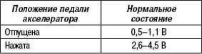
Press the accelerator pedal, then check that the values «Accelerator POS No.1» and «Accelerator POS No.2» match the nominal.
Rated values:
Accelerator POS No.1
Accelerator POS No.2
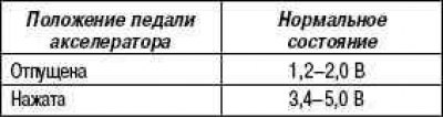
If the result is not normal, check the accelerator pedal, wiring harness and engine ECU.
Check of the oil valve of management of the mechanism of change of phases of gas distribution assy
Check resistance.
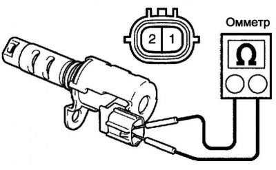
Pic. 2.539. Resistance measurement
Measure the resistance between the terminals with an ohmmeter (pic. 2.539).
Rated value
If the result is not normal, replace the variable valve timing control oil valve.
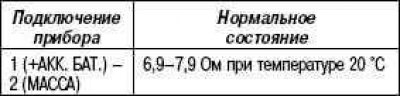
Check node operation.
Pic. 2.540. Checking the spool valve
Apply battery voltage to the terminals, then verify that the spool valve is working (pic. 2.540).
Note. Check if the spool valve is stuck.
Attention! The spool valve may not return to its original state if foreign objects get into it. This can cause the advance side pressure to build up slowly, resulting in a DTC.
Checking the mass air flow meter
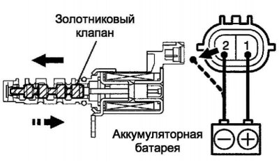
Check functionality.
Apply battery voltage to terminals 1 (+B) and 2 (E2G).
Pic. 2.541. Checking the operation of the mass air flow meter
Connect positive (+) voltmeter probe to terminal 3 (VG), and the negative (–) probe - to terminal 2 (E2G) (pic. 2.541).
Apply air to the mass flow meter, then check if the voltage changes.
If the voltage does not change, replace the mass air flow meter.
Check resistance.
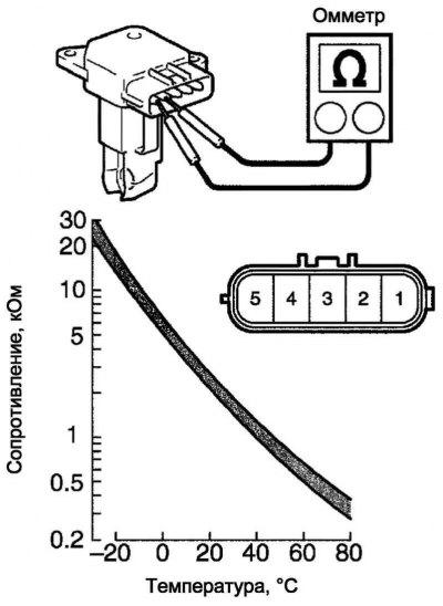
Pic. 2.542. Checking the resistance of the air mass meter
Measure the resistance between the terminals with an ohmmeter (pic. 2.542).
Verification conditions
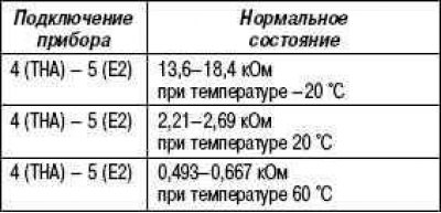
If the result is not normal, replace the mass air flow meter.
Checking the Engine Coolant Temperature Sensor
Check resistance.
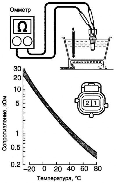
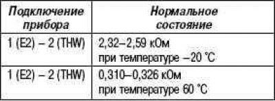
Pic. 2.543. Engine Coolant Temperature Sensor Resistance Check
Measure the resistance between the terminals with an ohmmeter (pic. 2.543).
Note. When checking the engine coolant temperature sensor in water, do not allow water to enter the terminals. After checking, it is necessary to remove water from the sensor.
If the result is not normal, replace the engine coolant temperature sensor.
Verification conditions
Checking the throttle body assembly
Check resistance.
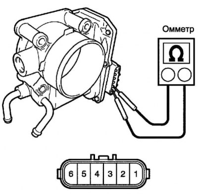
Pic. 2.544. Throttle body resistance test
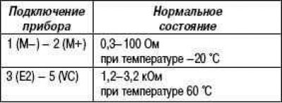
Measure the resistance between the terminals with an ohmmeter (pic. 2.544).
If the result is not normal, replace the throttle body.
Verification conditions
Checking the knock sensor
Check resistance.
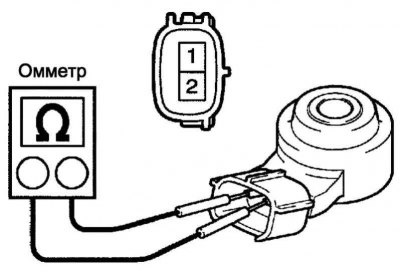
Pic. 2.545. Throttle body resistance test
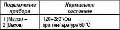
Measure the resistance between the terminals with an ohmmeter (pic. 2.545).
Verification conditions
If the result is not normal, replace the knock sensor.
Checking the accelerator pedal assembly
Check resistance.
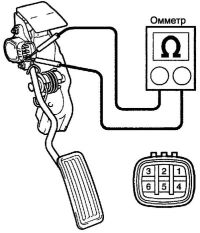
Pic. 2.546. Accelerator pedal resistance test
Measure the resistance between the terminals with an ohmmeter (pic. 2.546).
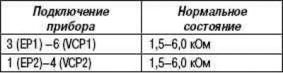
Verification conditions
If the result is not normal, replace the accelerator pedal.
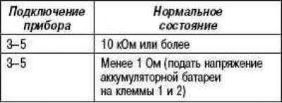
Checking the main relay
Check resistance.
Pic. 2.547. Checking the resistance of the main relay
Measure the resistance between the terminals with an ohmmeter (pic. 2.547).
Verification conditions
If the result is not normal, replace the main relay.
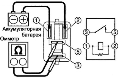
Checking the circuit opening relay
Check resistance.
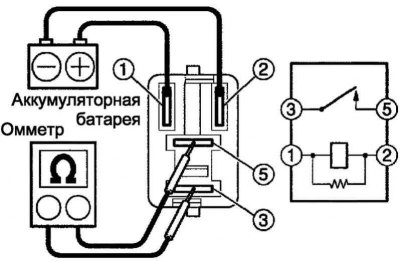
Pic. 2.548. Checking the resistance of the circuit opening relay
Measure the resistance between the terminals with an ohmmeter (pic. 2.548).
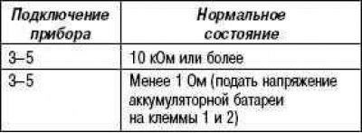
Verification conditions
If the result is not normal, replace the circuit opening relay.
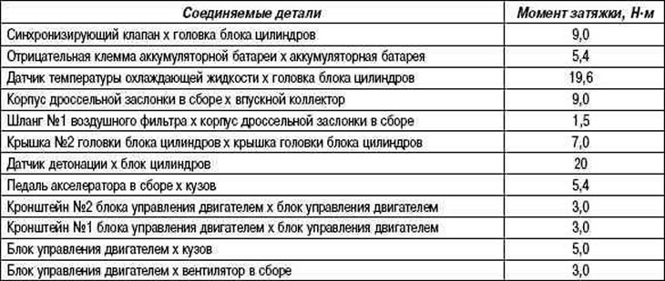
Table 2.33. Technical data for inspection and adjustment work (engines 1ZZ-FE / 3ZZ-FE)
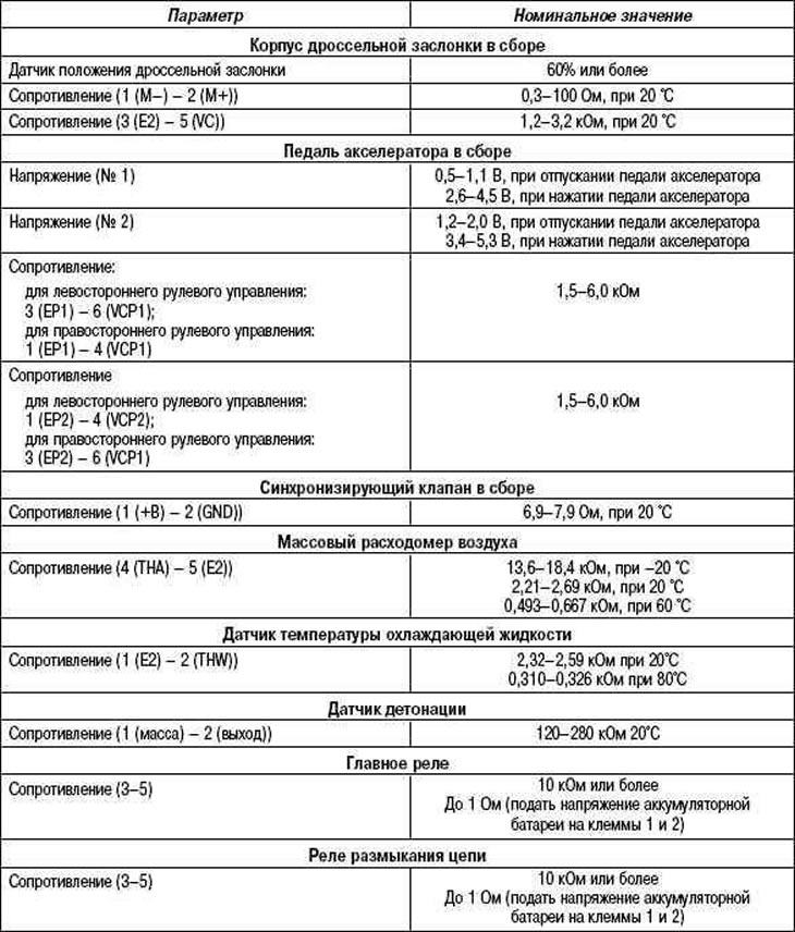
Table 2.34. Rated tightening torques (1ZZ-FE / 3ZZ-FE)