Checking the mass air flow meter (using a portable diagnostic tool II)
Check node operation.
Connect the handheld diagnostic tool II to the DLC3 diagnostic socket.
Turn the ignition ON (IG) and turn on the portable diagnostic tool II.
Select instrument mode: Powertrain/ Engine and ECT/ Data List/ MAF.
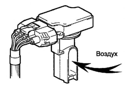
Pic. 2.549. Air supply
Apply air to the mass flow meter, then check if the MAF value changes in the data list (pic. 2.549).
Turn off the ignition (OFF) and turn off the portable diagnostic tool II.
Disconnect the portable diagnostic tool II.
If the operation is not normal, check the mass air flow meter, wiring and engine ECU.
Checking the air damper (when using the portable diagnostic tool II)
Check node operation (throttle position sensor).
Connect the handheld diagnostic tool II to the DLC3 diagnostic socket.
Turn the ignition ON (IG) and turn on the portable diagnostic tool II.
Select instrument mode: Powertrain/ Engine and ECT/ Data List/ Accel Open SW.
Throttle Position Sensor: On (ON)
Turn off the ignition (OFF) and turn off the portable diagnostic tool II.
Disconnect the portable diagnostic tool II.
If the result is not normal, check the accelerator pedal position sensor, wiring harness and engine ECU.
Check voltage (throttle position sensor).
Check the throttle position sensor with an oscilloscope.
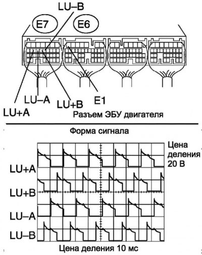
Pic. 2.550. Checking voltage with an oscilloscope
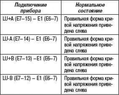
At idle, check the shape of the voltage waveform between terminals E7 and E6 of the engine ECU (pic. 2.550).
Verification conditions
If the result is not normal, check the accelerator pedal position sensor, wiring harness and engine ECU.
After checking, carry out a test drive.
Carry out a road test and verify that there are no faults.
Checking the Accelerator Pedal Position Sensor (using a portable diagnostic tool II)
Check the accelerator pedal position sensor.
Connect the handheld diagnostic tool II to the DLC3 diagnostic socket.
Turn the ignition ON (IG) and turn on the portable diagnostic tool II.
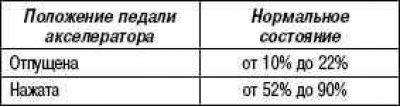
Select instrument mode: Powertrain/ Engine and ECT/ Data List/ Accel Position.
Check that the relative value of the accelerator pedal position (Accel Position) in the data list corresponds to the nominal.
Verification conditions
Turn off the ignition (OFF) and turn off the portable diagnostic tool II.
Disconnect the portable diagnostic tool II.
If the result is not normal, check the accelerator pedal position sensor, wiring harness and engine ECU.
Checking the mass air flow meter
Check functionality.
Apply battery voltage to terminals 1 (+B) and 2 (E2G).
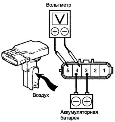
Pic. 2.551. Checking the operation of the mass air flow meter
Connect positive (+) voltmeter probe to terminal 3 (VG), and the negative (–) probe - to terminal 2 (E2G) (pic. 2.551).
Apply air to the mass flow meter, then check if the voltage changes.
If the voltage does not change, replace the mass air flow meter.
Check resistance.
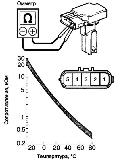
Pic. 2.552. Checking the resistance of the air mass meter
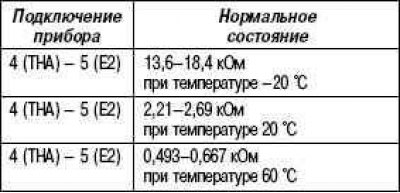
Measure the resistance between the terminals with an ohmmeter (pic. 2.552).
Verification conditions
If the result is not normal, replace the mass air flow meter.
Throttle valve assembly test
Check resistance (electric motor of the throttle valve drive).
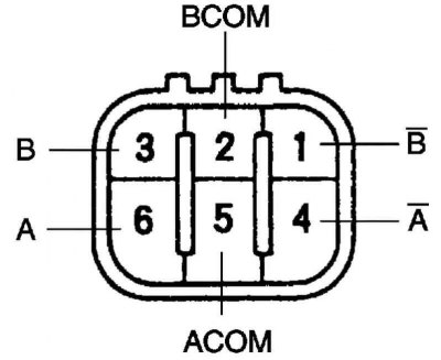
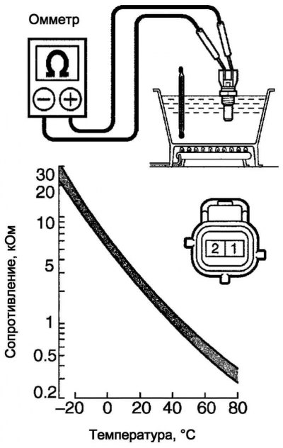
Pic. 2.553. Connector pins
Measure the resistance between the terminals with an ohmmeter (pic. 2.553).
Verification conditions
If the resistance is not within specification, replace the throttle body assembly.
Checking the Engine Coolant Temperature Sensor
Check resistance.
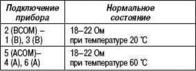
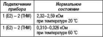
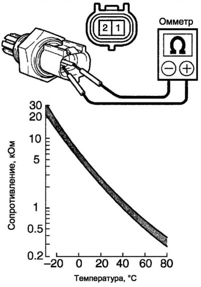
Pic. 2.554. Engine Coolant Temperature Sensor Resistance Test
Measure the resistance between the terminals with an ohmmeter (pic. 2.554).
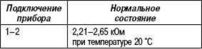
Verification conditions
Note. When checking the engine coolant temperature sensor in water, do not allow water to enter the terminals. After checking, it is necessary to remove water from the sensor.
Note. If the result is not normal, replace the engine coolant temperature sensor.
Checking the fuel temperature sensor
Check resistance.
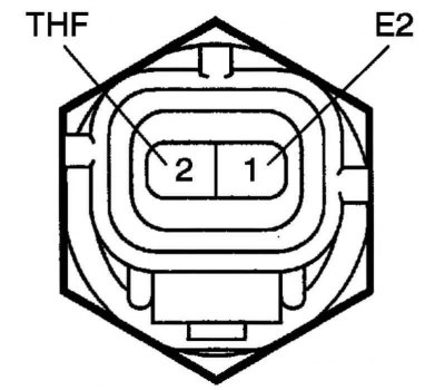
Pic. 2.555. Connector pins
Measure the resistance between the terminals with an ohmmeter (pic. 2.555).
Verification conditions
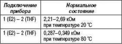
If the resistance is not normal, replace the fuel temperature sensor.
Checking the intake air temperature sensor
Check resistance.
Pic. 2.556. Checking the resistance of the intake air temperature sensor
Measure the resistance between the terminals with an ohmmeter (pic. 2.556).
Verification conditions
If the resistance is not normal, replace the intake air temperature sensor.
Checking the camshaft angle sensor
Check resistance.
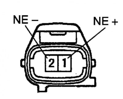
Pic. 2.557. Connector pins
Measure the resistance between the terminals with an ohmmeter (pic. 2.557).
Verification conditions
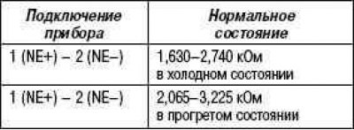
Note. The above notation «Cold» and «Hot» refer to the temperature of the sensor coils. State «Cold» (cold engine) corresponds to temperatures from -10°C to 50°C; «Hot» (warm engine) – from 50°C to 100°C. If the resistance is not normal, replace the camshaft angle sensor.
Checking the crankshaft angle sensor
Check resistance.
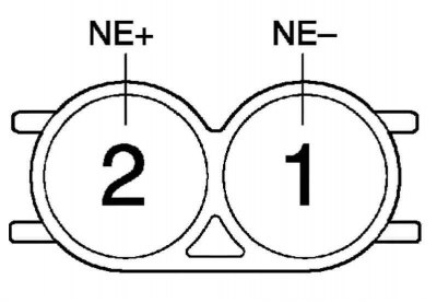
Pic. 2.558. Connector pins
Measure the resistance between the terminals with an ohmmeter (pic. 2.558).
Verification conditions
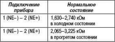
Note. The above notation «Cold» and «Hot» refer to the temperature of the sensor coils. State «Cold» (cold engine) corresponds to temperatures from -10°C to 50°C; «Hot» (warm engine) – from 50°C to 100°C. If the resistance is not normal, replace the crank angle sensor.
Checking the EDU relay
Check resistance.
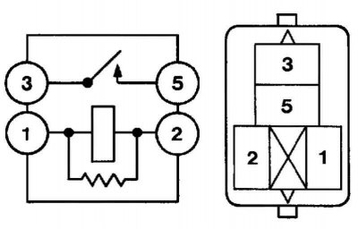
Pic. 2.559. Connector pins and test circuit
Measure the resistance between the terminals with an ohmmeter (pic. 2.559).
Verification conditions
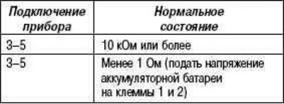
If the result is not normal, replace the EDU relay.
Checking the EFI main relay
Check resistance.
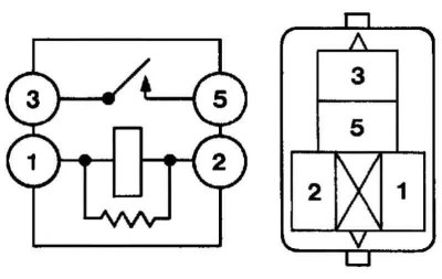
Pic. 2.560. Connector pins and test circuit
Measure the resistance between the terminals with an ohmmeter (pic. 2.560).
Verification conditions
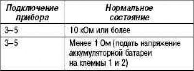
If the result is not normal, replace the EFI main relay.
Checking the accelerator pedal assembly
Check the accelerator pedal position sensor.
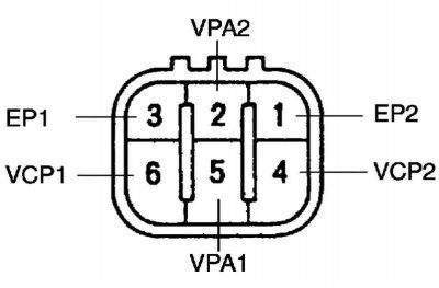
Pic. 2.561. Connector pins
Measure the resistance between the terminals with an ohmmeter (pic. 2.561).
Verification conditions
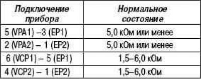
If resistance does not correspond to a normal condition, a pedal of an accelerator replace.
Table 2.35. Technical data for inspection and adjustment work (1CD-FTV engine)
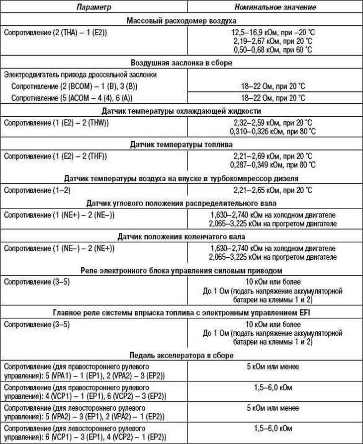
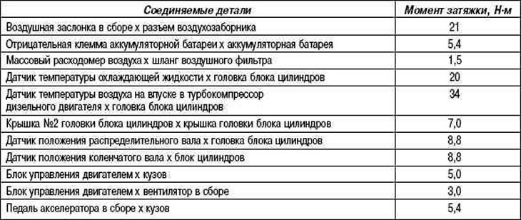
Table 2.36. Rated tightening torques (1CD-FTV)