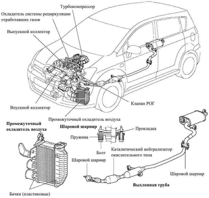
Pic. 2.74. 1CD-FTV engine intake and exhaust system
The engine is equipped with an intake manifold with channels of the same length and with a receiver to reduce the turbulence of the air flow distributed over the cylinders.
In the intake tract there is a throttle valve driven by a stepper motor. This solution improves the performance of the exhaust gas recirculation system (HORN), and reduce vibration when the engine is turned off.
The intercooler lowers the charge air temperature, thereby improving engine performance and reducing exhaust emissions.
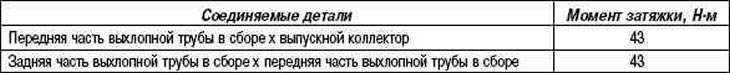
The exhaust manifold with the front part of the exhaust pipe, as well as the rear and front parts of the exhaust pipe, are connected by ball joints, which have a simple and reliable design.
Differences from previous models
Exhaust gas Recirculation valve (HORN) equipped with a stepper motor. Therefore, the vacuum valve and the VSV solenoid valve are excluded from the design (to turn off recirculation).
A liquid cooler for the EGR system has been installed.
The engine is equipped with a variable geometry turbocharger and an air intercooler.
The exhaust manifold has an oversized oxidation-type catalytic converter that complies with the requirements of Euro IIIY standards.
Exhaust gas recirculation system (HORN)
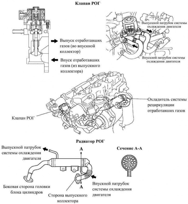
Pic. 2.75. 1CD-FTV engine exhaust gas recirculation system
The EGR system is designed to reduce the formation of oxides of nitrogen by slightly reducing the maximum temperature in the engine's combustion chamber while adding a small amount of exhaust gases to the intake manifold.
The cylinder head has an EGR channel, a liquid cooler is used to cool the exhaust gases, which reduces the temperature of the exhaust gases and allows more of them to be sent to the intake system.
The engine ECU directly controls the EGR valve (HORN) using a stepper motor.
Cooling of the EGR valve is provided by the circulation of the coolant in a special channel.
Turbocharger
Pic. 2.76. 1CD-FTV engine turbocharger
Changing the flow section of the turbocharger to maintain the optimal flow rate of exhaust gases entering the turbine blades in all operating modes made it possible to achieve a significant increase in torque at low speeds, increase maximum power and efficiency, as well as reduce noise and exhaust gas toxicity.
The geometry changer actuator is controlled by the vacuum controlled by the VRV valve in accordance with the signals received from the engine ECU.
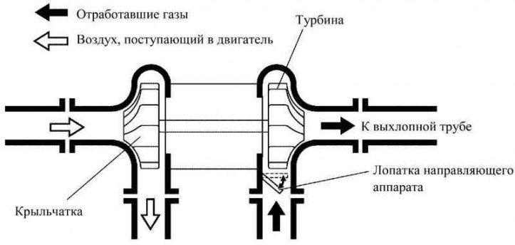
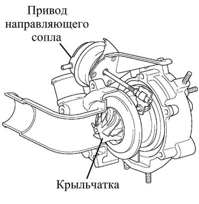
Pic. 2.77. Scheme of the turbocharger
Exhaust gases from the exhaust manifold enter through a nozzle with a variable flow area in the turbocharger housing to the turbine and then to the exhaust pipe (pic. 2.77). Turbine speed (boost pressure) varies depending on the flow rate of the exhaust gases passing through the turbine. The flow rate is controlled by the turbocharger guide vanes. At low engine speed (e.g. at idle) and, accordingly, a small amount of exhaust gases, the nozzle is almost completely closed. However, a small gap remains between the blades through which the exhaust gases enter the exhaust pipe. Thus, there is no bypass on the turbocharger.
Design features
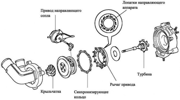
Pic. 2.78. Turbocharger components
The turbocharger consists of an impeller, a turbine, a guide nozzle drive, guide vanes and a timing ring (pic. 2.78).
Maintenance recommendation
In connection with the use of a variable geometry turbocharger, the verification procedures and control values have been changed. In addition, this turbocharger has a non-separable design.
Principle of operation (light load mode)
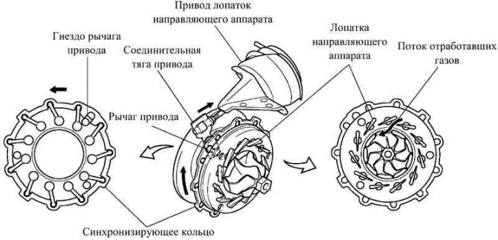
Pic. 2.79. Light load mode
When the engine is running under light load, the actuator moves the tie rod up on a signal from the engine ECU. The drive lever connected to the rod turns the timing ring clockwise. The connecting ring moves the driven arm connected to it in the same direction. A guide vane located behind the plate is installed on the axis of rotation of the driven lever. When the driven lever is rotated counterclockwise, the guide vanes turn and reduce the nozzle flow area, increasing the flow rate of exhaust gases entering the turbine, and maintaining the required frequency of its rotation. Due to this, the performance of the engine at low loads is improved.
Principle of operation (high load mode)
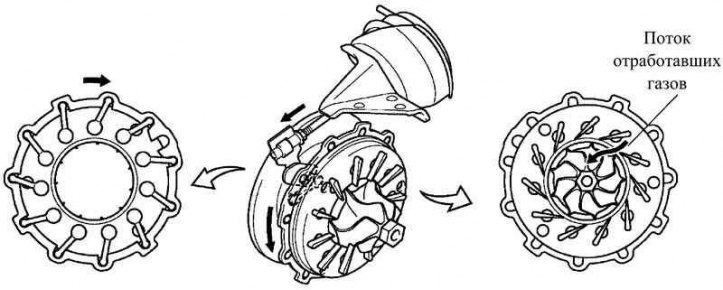
Pic. 2.80. High load mode
When the engine is under heavy load, the actuator moves the tie rod down on a signal from the engine ECU. At the same time, the drive lever moves clockwise and rotates the guide vanes, increasing the nozzle flow area and maintaining the set boost pressure. This reduces exhaust backpressure, improves performance and reduces fuel consumption.
Catalytic converter integrated in the exhaust manifold
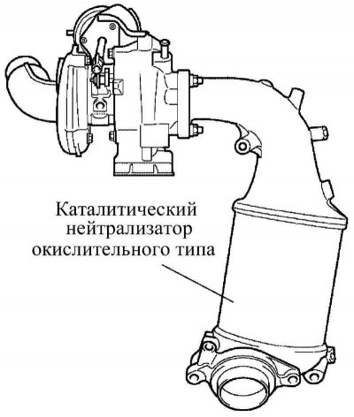
Pic. 2.81. Catalytic converter integrated in the exhaust manifold
The exhaust manifold has a higher capacity oxidation type catalytic converter that meets the requirements of Euro III standards.
Table 2.44. Technical data for inspection and adjustment work (1CD-FTV engine)
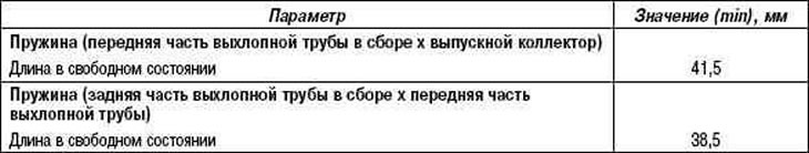
Table 2.46. Rated tightening torques (1CD-FTV)