
General information
In order to reduce the emission of toxic components into the atmosphere that enter the composition of the exhaust gases of the engine as a result of evaporation and incomplete combustion of the fuel, as well as to maintain the efficiency of the engine output and reduce fuel consumption, the vehicles covered in this manual are equipped with a number of special systems that can be combined under the general name of engine management systems and reducing the toxicity of exhaust gases. The complete set of systems depends on the year of manufacture of the models and the region in which the car is supplied to the market. Full information on the type of composition of the systems is given on the VECI information label fixed under the hood (see Introduction).
Note. The hose routing diagram can be shown on a separate nameplate.
Systems related to engine management and emission control include the following:
- Pulse air mixing system (PAIR);
- catalytic converter;
- Evaporative Emission System (EVAP);
- Exhaust gas recirculation system (EGR) – it is used only on diesel engines;
- Controlled crankcase ventilation system (PCV);
- On-Board Diagnostic System (OBD);
Note. More detailed information on the engine management and emission control systems of your vehicle can be obtained from the representative office of the manufacturer.
The functioning of all these systems, one way or another, directly or indirectly, is related to the management of the reduction of exhaust gas toxicity. The following Sections provide general descriptions of how each system operates, as well as procedures for diagnostic checks and remedial repairs (if it is possible) individual components, the performance of which lies within the qualifications of the average amateur mechanic
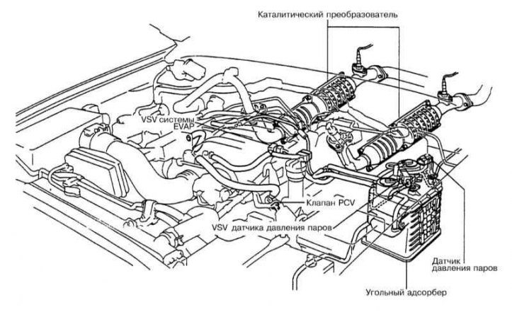
Scheme of laying vacuum lines on V8 models 1998 vol.
Scheme of laying vacuum lines on V8 models 1999-2000, no.
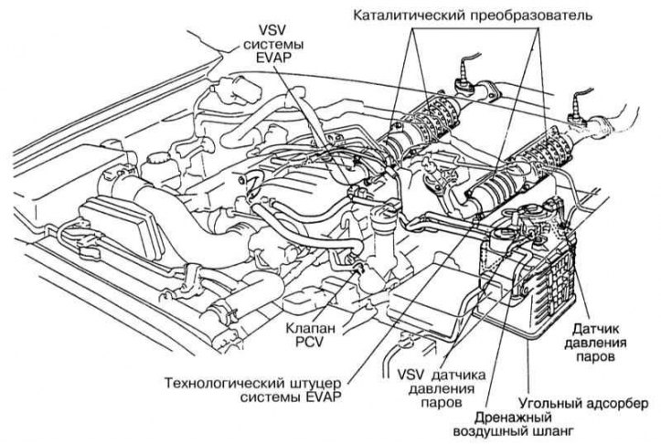
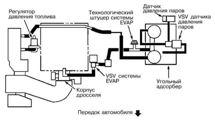
Diagram of laying vacuum lines on V8 models
Before coming to the conclusion that any of the emission control systems have failed, carefully check the power and ignition systems for proper functioning (see chapters Power supply and exhaust systems and Engine electrical equipment). Diagnostics of some of the components of toxicity reduction systems requires the use of special, difficult-to-use equipment and a certain qualification of the performer, and therefore, it would be reasonable to entrust its implementation to professional mechanics of a specialized service station. The foregoing does not mean that the maintenance and repair of components of toxicity reduction systems in practice seem difficult. It should be remembered that one of the most common causes of failures is an elementary violation of the quality of vacuum or electrical contact connections, and therefore, first of all, you should always check the condition of electrical connectors and union connections of vacuum lines (refer to the illustrations above). The owner of the car can independently and quite easily perform a number of checks, as well as perform many routine maintenance procedures for most system components at home, using the usual set of tuning and locksmith tools.
Note. Be aware of additional federal warranties that apply to emission control and engine management components. Before starting any repair procedures for components and parts of these systems, consult the conditions for compliance with these obligations at the representative office of Toyota.
Try to observe all the precautions specified in the following Sections when performing maintenance of the electronic components of the systems in question. It should be noted that the illustrative material may not always exactly match the actual placement of components on the vehicle. Such inconsistencies are associated with the ongoing process of modification within the framework of the typical design of each model.