
Engine coolant temperature sensor (EATING)
Attention! Wait until the engine has completely cooled down before proceeding with the procedure!
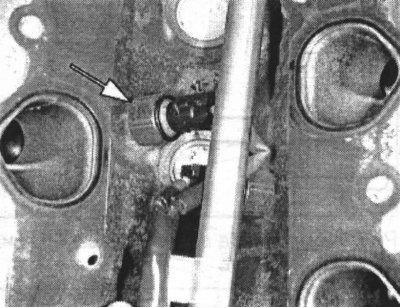
ECT Sensor Installation Components
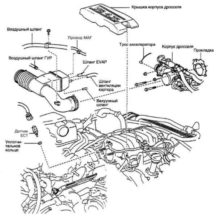
On V8 petrol models, the sensor is located under the throttle body cover (refer to illustration above) at the top of the intake manifold. The sensor replaces a thermistor, the resistance of which changes inversely with the temperature of the coolant. A description of the procedure for checking the sensor is given in Section Information sensors - general information and function check.
1. To remove the sensor, drain the coolant and remove the throttle body cover. Remove the intake duct flange from the throttle body. Remove the throttle body, for which disconnect the accelerator cable from it and give two bolts and two fastening nuts.
Note. The old gasket can be discarded - a new one is required for installation.
2. Disconnect the ECT sensor connector, then carefully unscrew the assembly from its seat.
Attention! Try to handle the ECT sensor with extreme caution - damage to it can affect the proper functioning of the entire power system.
Note. The old sensor o-ring can be discarded - a new one is required for installation.
3. Install a new sensor as soon as possible to minimize coolant loss. Tighten the sensor and throttle body fasteners to the specified torque. Finally, fill in the coolant, start the engine and check for leaks.
Air flow sensors
MAF sensor
The MAF sensor is placed inside the air intake sleeve. The sensitive element of the sensor is a filament. The sensor is used to determine the mass of air sucked into the engine per unit time. A description of the procedure for checking the sensor is given in Section Information sensors - general information and function check.
1. Disconnect the electrical wiring from the MAF sensor and separate the air cleaner assembly from the air intake sleeve (see chapter Power supply and exhaust systems).
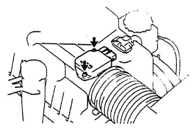
2. Give the fixing screws and remove the MAF sensor assembly from the air cleaner (refer to accompanying illustration).
3. Installation is carried out in the reverse order.
IAT sensor
The IAT sensor is integrated into the MAF sensor housing and cannot be replaced separately.
Lambda probes
Note. Due to thermal compression of the components of the exhaust system when it cools, removing the lambda probe may be fraught with certain difficulties. To avoid the risk of damaging the sensor when removing it, preheat the engine for one to two minutes. Be careful not to burn yourself.
On V8 models, 4 lambda probes are installed, - two top-flow mounted in front (downstream) catalytic converters and two downstream ones screwed into the system section below (downstream) catalytic converters. Sensors monitor the level of oxygen in the exhaust gases of the engine. A description of the design and procedure for checking sensors is given in Section Information sensors - general information and function check.
When servicing lambda probes, special precautions should be observed:
- The lambda probe is equipped with a piece of electrical wiring permanently mounted into it, equipped with a contact plug, attempts to disconnect which can lead to irreversible failure of the probe;
- Try to keep the probe shutters or electrical connector free of dirt and grease;
- Do not use any solvents to clean the lambda probe;
- Handle the lambda probe with extreme care, do not drop it and try not to shake it off;
- The silicone protective cover must be worn on the sensor in a strictly defined way so as not to be melted and not to impair the proper functioning of the probe.
1. Disconnect the negative cable from the battery.
Attention! If the stereo system installed in the car is equipped with a security code, before disconnecting the battery, make sure that you have the correct combination to activate the audio system!
2. Jack up the car and put it on stands.
3. Remove the heat shields that block access to the oxygen sensor to be serviced. Disconnect wiring from sensor.
4. Carefully unscrew the bolts securing the lambda probe to the exhaust system element (exhaust manifold or exhaust pipe).
5. When installing the probe, the threads of the probe should be lubricated with an anti-seize sealant.
Note. The threads of a new sensor are usually already treated with the appropriate compound.
6. Install the probe in its proper place and tighten it firmly.
7. Restore the original wiring connection.
8. Lower the vehicle and test drive it. Make sure there are no trouble codes in the OBD memory.
Throttle position sensor (TPS)
TPS Location and Mounting
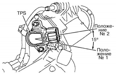
The TPS is a variable resistance potentiometer mounted on the throttle body and connected directly to the throttle shaft (refer to illustration above). A description of the TPS design and verification procedure is given in Section Information sensors - general information and function check.
1. Disconnect the wiring from the sensor.
Note. It may be necessary to remove the air intake duct in order to gain access to the sensor connector.
2. Remove the mounting screws and remove the TPS from the throttle body.
3. When installing the sensor, make sure that the guide tabs fit into the reciprocal grooves on the throttle axis. Check TPS sensor.
4. Installation is carried out in the reverse order.
Crankshaft position sensor (TFR)
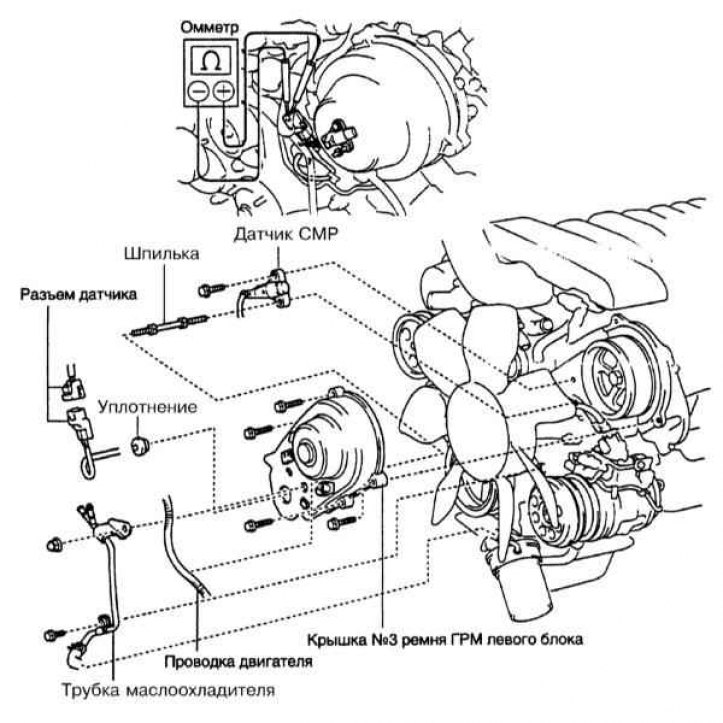
Installation Components and Checking the CKP Sensor
1. The location of the CKP sensor is shown in the illustration above. In order to provide access to the mounting bolt, remove the crankcase protection. Disconnect the electrical wiring from the sensor and give the bolt of its fastening to the oil pump.
2. Installation is carried out in the reverse order. Tighten the sensor mounting bolt to the required torque.
Camshaft position sensor (TFR)
1. The sensor is installed in the left cylinder head (refer to illustration above). In order to gain access to the mounting bolt, drain the coolant and remove the accessory drive belts. Disconnect from the gauge electroconducting and give a bolt of its fastening and a hairpin.
2. Installation is carried out in the reverse order. Tighten the sensor mounting bolt to the required torque.
Knock sensors
Attention! Wait until the engine has completely cooled down before proceeding with the procedure.
Note. On 2UZ-FE engines, one knock sensor is installed on each cylinder head.
The location of the knock sensor is shown in the accompanying illustration.
1. To remove the knock sensor, drain the coolant and remove the intake duct.
2. Remove the timing belt cover covering the camshaft gears.
3. Remove the top part of the inlet pipeline and a regulator of pressure of fuel.
4. Remove the inlet pipeline.
5. Remove the water bypass tube and disconnect the sensor wiring. Remove sensors.
6. Installation is carried out in the reverse order. Having screwed in the sensors, tighten with the required force. Fill with coolant.
Vehicle speed sensor (VSS)
A description of the construction and verification procedure of the VSS is given in Section Information sensors - general information and function check.
1. Turn out fixing bolts, disconnect electroconducting and remove the gauge.
2. Installation is carried out in the reverse order.