
Attention! To avoid damage to the ECM, use only a high voltage digital voltmeter when performing the following checks (over 10 MΩ) impedance!
Attention! A car equipped with an OBD-II system should be driven to a service station for reading fault codes using a special scanner. There are only a few checks (related to identifying the causes of failures when starting the engine), which the owner of the vehicle can perform on his own, in all other cases the car should be driven to a car service.
2-pin thermistors (temperature sensors for coolant, intake air, etc.)
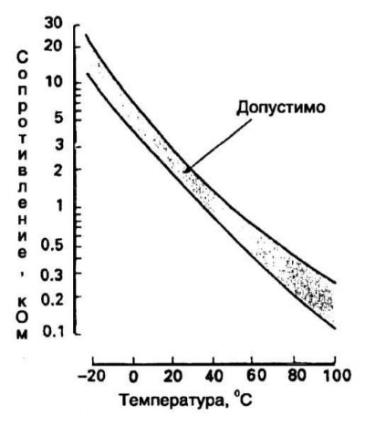
Thermistors are resistors that change resistance with temperature and produce a corresponding signal voltage. These types of elements include engine coolant temperature sensors (EATING) and intake air temperature (IAT). It should be noted that the resistance of these sensors changes inversely with the change in temperature, i.e., DECREASES with an INCREASE of the latter, and vice versa. To test thermistor sensors, switch the multimeter to resistance measurement, disconnect the wiring from the sensor and measure the resistance between the assembly terminals. Measure the temperature. Then warm up the sensor to a certain temperature and measure its resistance again. Compare your results with those prescribed. The location of the ECT sensor is shown in the illustration below. The IAT sensor is built into the MAF sensor. For the IAT sensor, the resistance between terminals E2 and THA of the MAF sensor is measured.
Plot of ECT and IAT sensor resistance versus temperature
ECT Sensor Installation Components
Next, you should check the correctness of the reference voltage supplied to the sensor by the processor. Connect the wiring to the sensor, switch the multimeter to measure voltage and connect its probes to the wiring harness terminals on the connector. The nominal value of the reference voltage should be about 5.0 V. The check is carried out with the ignition on, do not start the engine. If there is a malfunction in the reference voltage supply to the sensor, the condition of the connecting wiring and the ECM itself should be checked.
Potentiometers (throttle position sensor)
A potentiometer is a resistor whose resistance changes as a result of the mechanical movement of some components. The TPS sensor generates a signal voltage proportional to the current value of the potentiometer resistance, determined by the position of the throttle in the throttle body. The signal from the sensor is sent to the ECM, which, based on the analysis of incoming data, determines the position and direction of movement of the damper. To check the correct functioning of the TPS sensor, the nature of the change in the resistance value of the potentiometer is quantified depending on the degree of opening of the throttle valve. This circuit is defined as VTA - E2.
1. Disconnect wiring from TPS. On eligible models, disconnect the vacuum line and apply a vacuum to the throttle positioner using a hand held vacuum pump. Using an ohmmeter, measure the resistance between terminals VTA and E2 of the TPS sensor (refer to accompanying illustration). With the damper fully closed, the resistance should be in the range from 0.2 to 5.7 kOhm, and with the damper fully open, the ohmmeter should show infinity.
2. Next, check the correctness of the reference voltage supplied to the sensor by the processor. Connect the wiring to the sensor, switch the multimeter to measure voltage and connect its probes to the corresponding terminals of the wiring harness on the connector. The voltage at the sensor terminals with the throttle opening should increase: with the damper fully closed, it should be within 0.7 V, and with the damper fully open, it should be 2.7–5.2 V. ECM.
2-pin electromagnetic sensors (crankshaft and camshaft position sensors and vehicle speed sensor)
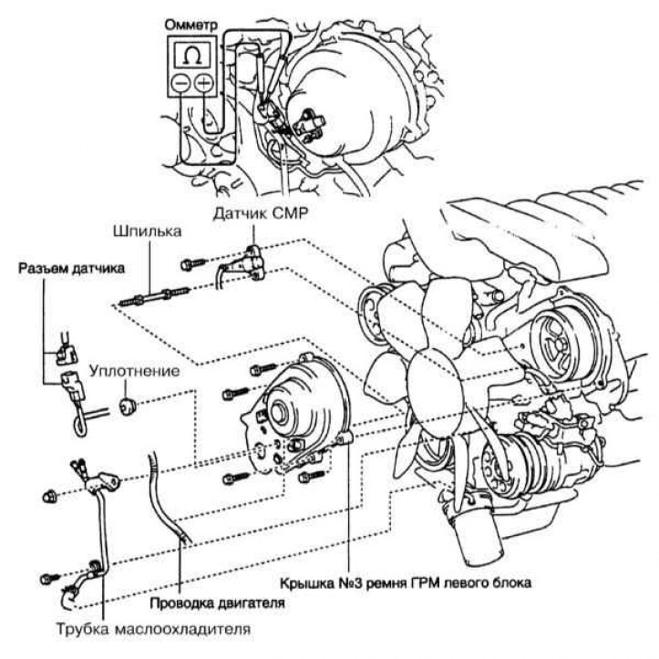
The design of electromagnetic sensors is based on a permanent magnet placed inside the wire winding. Typical representatives of electromagnetic sensors are crankshaft and camshaft position sensors (TFR and SMR), as well as a vehicle speed sensor (VSS). The steel disk fixed on the gear is equipped with tongues passing between the pole ends of the magnet and causing the magnetic field to close. Fluctuations in the magnetic field lead to a change in the signal voltage of the sensor. Based on the analysis of the signals coming from the sensors, the ECM determines the speed of the vehicle (VSS), or the current position of the corresponding shaft (TFR and SMR). The CKP sensor generates a G signal for the ECU. The location and test patterns of the sensors are shown in the illustrations below.
Installation Components and Checking the CMP Sensor
Checking the CKP sensor
Location of the CKP sensor
VSS Sensor Location
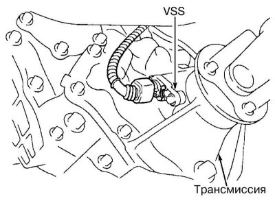
To test the CKP and CMP sensors, measure the resistance between their connector terminals. On a cold engine (temperature below 53 degrees.) on the CMP sensor, the resistance should be 835-1400 ohms, and on the CKP sensor: 1630-1740 ohms. On a warm engine (temperature 53 00 deg.) on the CMP sensor, the resistance should be 1060-1645 ohms, and on the CKP sensor - 2065-3225 ohms. In the case of VSS, the transmission must first be brought to a neutral position, then, holding one wheel stationary, manually rotate the opposite (use the help of an assistant), it is necessary to simulate a speed of about 3.5 km / h, observe the meter readings. This check can also be made on the sensor removed from the vehicle - the drive gear of the assembly will have to be rotated.
Note. VSS without drive gear is used on some models, these sensors must be tested in situ (without removal from the car). When checking the TFR sensor, you will also need the help of an assistant, who will have to crank the engine with a starter in short jerks, follow the readings of the voltmeter, which should register weak uniform fluctuations, confirming the health of the state and functioning of the magnetic part of the sensor.
Lambda probes
O2 sensors, or lambda probes, monitor the percentage of oxygen in the engine's exhaust gases. O2 molecules present in the exhaust system, reacting with the sensitive element of the sensor, cause the latter to generate a signal voltage. The signal amplitude, depending on the oxygen concentration, can range from 0.1 V (high O2 content, lean air-fuel mixture) up to 0.9 V (low O2, rich mixture). The ECM continuously monitors the signal coming from the lambda probe, and based on the incoming data, it makes the appropriate adjustments to the air-fuel composition, trying to maintain it at an optimal level (14.7 parts of air to 1 part of fuel, - stoichiometric number). The composition of the mixture is adjusted by controlling the duration of the opening time of the injectors. The lambda probe only begins to generate a signal voltage after it has warmed up to its normal operating temperature of approximately 320°C. With that said, the ECM operates in open loop during the engine warm-up process. Do not forget to check the condition of all lambda probes included in the system.
Note. Access to lambda probes is usually difficult. Be careful, remember that exhaust system components can remain hot for a long time after the engine has stopped and pressing wire harnesses against their surface can lead to destruction of their insulation. Try, if possible, to check the components of the system using a scanner connected to the DLC connector, the device allows you to detect changes in the signal voltage of each of the lambda probes within thousandths of a volt.
1. Check the millivolt output generated by the transducer. Find the electrical wiring connector and, on its reverse side, carefully connect the voltmeter probes to the corresponding contact terminals. On most models, the positive probe is connected to the signal terminal of the sensor connector (SIGNAL), and negative - grounding lemma (see Onboard electrical equipment).
Note. Fluctuations in the signal voltage of low-flow lambda probes are much slower than those of high-flow ones, which is explained by the result of the operation of a catalytic converter that converts carbon monoxide, hydrocarbons and nitrogen oxides present in the exhaust gases into non-toxic carbon dioxide and water, the oxygen of which reacts to a much lesser extent with the sensitive sensor element.
2. With a cold engine, in open circuit mode, the lambda probe generates a stable amplitude signal in the range of 0.1–0.2 V. After about two minutes, the sensor enters the operating temperature mode and the amplitude of its signal voltage begins to fluctuate in the range from 0.4 to 0.6 V, depending on the oxygen content in the exhaust gases. If the sensor enters the operating mode too slowly, or does not go out at all, as well as when the voltage stabilizes in the middle of the operating voltage range, the sensor should be replaced. If the sensor output voltage has stabilized near one of the limits of the specified range, it is likely that the ECM is not able to compensate for mechanical engine problems such as air leakage or «pouring» injectors.
Note. Do not forget that the downstream lambda probe is noticeably slower than the upstream one (see below).
3. Pull off the vacuum hose behind the throttle. The voltage should drop to approximately 0.12V (still changing rapidly). This tests the sensor's ability to recognize a lean mixture. Attach the hose in place.
4. Richen the mixture by applying gas to the intake tract with a propane gun. The voltage should rise to approximately 0.9V (still changing rapidly). This tests the sensor's ability to detect an over-rich mixture.
5. If the sensor output voltage is above or below the specified limits, the sensor or its wiring is faulty. Check the integrity of the wiring and, if necessary, repeat the test.
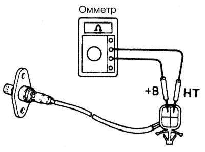
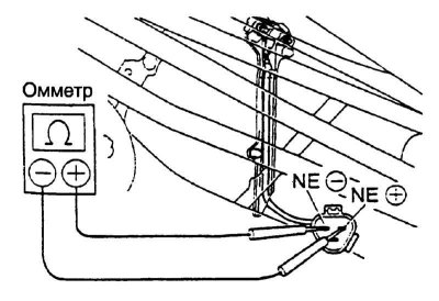
6. Check up also serviceability of functioning of a chain of a heater of a lambda probe. Disconnect the electrical wiring from the sensor and connect an ohmmeter to the contact terminals B (+) and NT (-) connector on the sensor side (refer to accompanying illustration). Compare the measurement result with the requirements Specifications. Please note that the upstream and downstream sensors are not interchangeable. Next, you should check the correctness of the power supply to the sensor heater circuit, - disconnect the wiring and connect a voltmeter to the connector on the side of the harness: with the ignition on (do not start the engine) battery voltage must be present at the connector terminals. If necessary, check the condition of the circuit between the sensor and the fuse/main relay. Replace defective sensor (see wiring diagrams at the end Onboard electrical equipment).
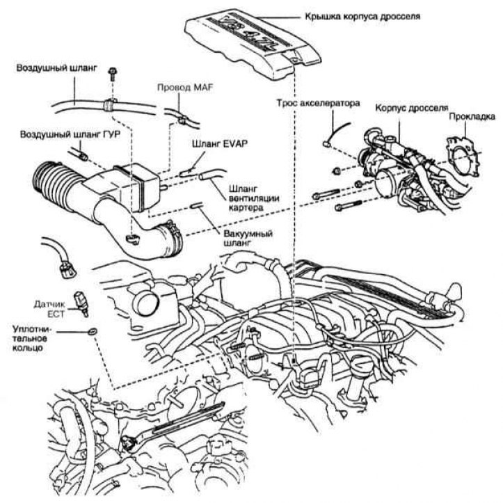
Air mass measurement sensor
The sensor is used to measure the flow rate of air sucked into the throttle body. The ECM uses information from the sensor to adjust the length of time the injectors are opened - the more air is sucked into the engine (acceleration), the more fuel the latter needs. On the models under consideration, vortex-type air flow sensors with a filament-based sensing element are used. The device allows you to determine the weight flow rate and is called the air mass sensor (MAF). Based on the information coming from the sensor, the ECM makes timely adjustments to the composition of the air-fuel mixture.
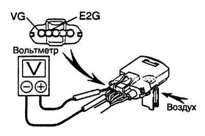
Models covered in this manual use 5-pin type MAF sensors. For them, remove the intake duct and turn on the ignition. Connect the positive voltmeter lead to VG and the negative lead to E3 (refer to accompanying illustration). Blow into the sensor and check for a change in voltage.
Knock sensors
Note. V8 petrol models use two knock sensors, one on each cylinder head (under intake manifold).
The knock sensors detect the increased intensity of engine vibrations that occur when the air-fuel mixture is detonated, and provide the appropriate information to the control module, allowing the ECM to perform a knock-suppressing reduction in the ignition timing in a timely manner.
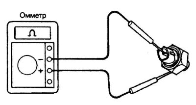
To check the condition of the knock sensor, disconnect the electrical wiring from it and measure the resistance between the contact terminal of the connector and the mass of the assembly housing, there should be no conductivity (refer to accompanying illustration). Replace defective sensor.
Start enable switch (models with AT)
The start enable switch is installed on the rear of the transmission dome, in its upper part, and serves to notify the ECM of the fact that the AT is in the positions «R» and «N». This information is used by the processor when controlling the operation of the idle speed stabilization system.
Attention! To avoid idle stability problems, do not drive with the start enable switch disconnected.
More detailed information on the principle of operation of the start enable sensor-switch is set out in Chapter Gear box.
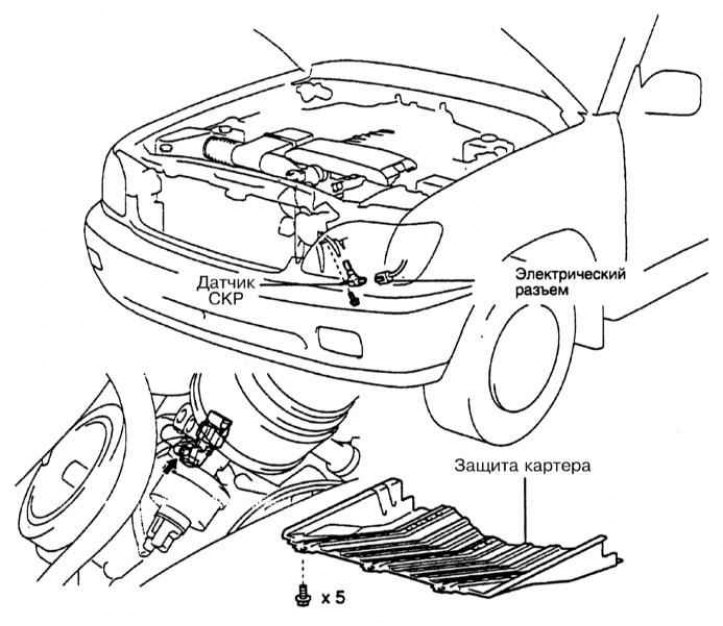
Fuel vapor pressure sensor
The sensor is used to monitor the pressure / depth of depression in the fuel tank. Based on the information coming from the sensor, the ECM timely detects the fact that the purge of the carbon canister of the EVAP system is malfunctioning and enters the corresponding diagnostic code into the OBD-II memory. The performance of work to restore the correct functioning of the EVAP system should be entrusted to car service specialists.