
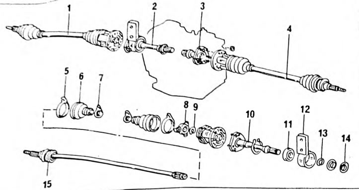
Pic. 182. Details of drive shafts in the presence of intermediate shafts; 1. Right drive shaft; 2. Intermediate shaft; 3. Differential output shaft; 4. Left drive shaft; 5. Cuff clamp; 6. Rubber cuff; 7. Cuff clamp; 8. Cross; 9. Retaining ring; 10. Intermediate shaft; 11. Ball bearing; 12. Support console; 13. Retaining ring; 14. Boot ring; 15. Outer joint and drive shaft.
If it is necessary to remove the drive shaft, then proceed as described above, but on one side the flange connection of the intermediate shaft must be released. After this, unscrew the shaft support from the cylinder block and pull out the shaft, as shown in Figure 183. The intermediate shaft can be disassembled into the parts shown in Figure 182. First of all, remove the support bracket and the middle bearing (Pic. 184) . After this, press out the inner and outer rings of the anthers. Remove the bearing retaining ring and press the bearing off the shaft. Press the new bearing onto the shaft and secure it with a small retaining ring. Then press the dust seals into the cantilever supports. Install the support console onto the intermediate shaft.
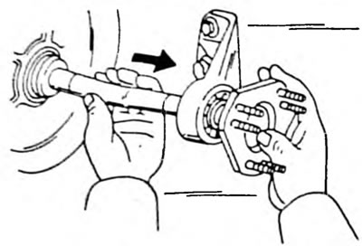
Pic. 183. Pull the intermediate shaft out of the gearbox using the method shown
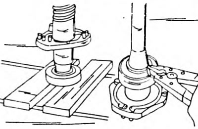
Pic. 184. A retaining ring holds the ball bearing on the intermediate shaft. On the left side the bearing is pressed onto the shaft.